

Steam Sterilization Temperature Mapping and Penetration
Steam sterilization temperature mapping generates physical evidence that a sterilizer and defined cycle establish the required thermal conditions throughout the chamber and at difficult-to-heat locations within the load.
The term “temperature mapping” is often used broadly, but several different studies must be distinguished:
- Empty-chamber heat distribution evaluates thermal conditions within the unloaded chamber.
- Loaded-chamber heat distribution evaluates chamber-space conditions around a defined load.
- Load heat penetration evaluates temperature and lethality at critical locations within articles, packages, assemblies, pathways, or products.
- Biological-indicator studies evaluate a defined microbiological challenge at selected difficult-to-sterilize locations.
These studies answer related but different questions. Uniform empty-chamber conditions do not prove that steam penetrates a porous pack, reaches an internal equipment surface, heats the liquid cold zone, or delivers adequate lethality throughout a production load.
Purpose and Lifecycle Position
This article addresses:
- Mapping-study objectives and boundaries
- Empty-chamber heat distribution
- Loaded-chamber heat distribution
- Load and product heat penetration
- Study prerequisites
- Sensor quantity and placement
- Thermocouples, resistance sensors, and wireless data loggers
- Probe attachment and insertion
- Validation data-acquisition systems
- Calibration and measurement traceability
- Time synchronization and sampling intervals
- Exposure-phase determination
- Chamber equilibrium and load equilibration
- Cold-location and slowest-heating-location determination
- F₀ calculations
- Temperature and lethality acceptance criteria
- Maximum-exposure evaluation
- Repeatability
- Deviations, failed sensors, and invalid data
- Reporting and raw-data control
- Transfer of mapping conclusions into qualification and routine control
The scientific basis for saturated-steam heat transfer, air removal, condensate drainage, steam quality, liquid-load processes, and moist-heat lethality is addressed in Moist Heat Sterilization Principles and Cycle Types.
Load families, minimum and maximum loads, packaging, orientation, difficult-to-sterilize items, recipe development, and candidate sensor locations should be established during Steam Sterilization Load and Cycle Development.
Mapping then converts those development hypotheses into measured evidence:
Defined chamber, cycle, and load → justified sensor locations → controlled study execution → thermal-data analysis → cold-location determination → lethality evaluation → qualification conclusion
Distribution and Penetration Are Different Studies
The principal studies should be defined before protocols are written.
| Study | Configuration | Principal question | Typical measurements |
|---|---|---|---|
| Empty-chamber heat distribution | Chamber without a production load | Can the sterilizer establish controlled and reasonably uniform chamber conditions? | Chamber-space temperatures, drain temperature, pressure, control-sensor response |
| Loaded-chamber heat distribution | Chamber containing a defined load | How does the load affect chamber-space temperature distribution? | Temperatures around the load, drain temperature, pressure, control-sensor response |
| Load heat penetration | Sensors placed within or directly on load targets | How quickly and reproducibly does heat reach critical load locations? | Internal temperatures, heating lag, exposure time, F₀ |
| Product heat penetration | Sensors placed within a product or solution | Where is the lowest delivered lethality and highest relevant exposure? | Product temperature profile, F₀, heating and cooling behavior |
| Microbiological challenge | BIs or inoculated units at justified challenge locations | Does the process inactivate the defined biological challenge? | BI recovery, growth response, positive controls, applicable resistance data |
Loaded-chamber heat distribution and load heat penetration may be executed during the same cycle, but the resulting data should not be combined without preserving the purpose and identity of each sensor.
A chamber-space sensor measures the surrounding environment. A penetration sensor measures the response of a specific sterilization target. The chamber can reach the required exposure temperature before the load target does.
Study Prerequisites
Temperature mapping should begin only after the necessary equipment, cycle, documentation, and measurement-system prerequisites are available.
Prerequisites may include:
- Approved sterilizer system description
- Defined chamber boundary and dimensions
- Current piping and instrumentation diagrams
- Identification of steam entry, vent, drain, vacuum, and jacket connections
- Verified chamber-control and monitoring sensors
- Acceptable equipment calibration status
- Acceptable utility status
- Verified chamber leak-rate performance where applicable
- Verified air-removal capability where applicable
- Approved operating procedure
- Controlled cycle recipe
- Defined exposure-start logic
- Approved load-development information
- Controlled load diagram
- Defined minimum, maximum, or challenge load
- Approved packaging and orientation
- Defined sterilization target
- Required minimum lethality
- Defined maximum allowable exposure where applicable
- Approved biological-indicator strategy
- Calibrated validation instrumentation
- Qualified or otherwise suitable data-acquisition system
- Approved protocol with predefined acceptance criteria
- Trained study personnel
Engineering or development studies may be executed before all qualification prerequisites are complete, but they should be clearly identified as development work. Exploratory data should not automatically be represented as formal qualification evidence.
Study Protocol
The mapping protocol should define what will be measured, how it will be measured, and how the results will be evaluated before execution begins.
The protocol should include:
- Sterilizer identification
- Cycle name, number, and recipe version
- Study type
- Study objective
- Load-family identification
- Load configuration
- Minimum, maximum, or special challenge condition
- Item quantities and orientations
- Sensor type and identification
- Sensor quantity
- Sensor-location rationale
- Sensor-placement diagram
- Probe-attachment or insertion method
- Data-acquisition-system identification
- Sampling interval
- Calibration and verification requirements
- Time-synchronization method
- Exposure-phase definition
- Equilibrium or equilibration criteria
- Temperature acceptance criteria
- F₀ calculation method
- Lethality acceptance criteria
- Maximum-exposure criteria
- BI locations and acceptance criteria where applicable
- Required number of study runs
- Handling of failed, displaced, or questionable sensors
- Deviation requirements
- Required raw records and attachments
- Review and approval responsibilities
Acceptance criteria should be based on cycle-development evidence, product and load requirements, equipment capability, microbiological strategy, site procedures, and applicable regulatory commitments. Values should not be copied from another sterilizer or load without documented applicability.
Empty-Chamber Heat Distribution
Empty-chamber heat distribution evaluates the sterilizer’s ability to establish controlled thermal conditions without the influence of a production load.
The study may be used to:
- Evaluate spatial temperature distribution
- Compare independent validation sensors with the chamber-control system
- Observe the chamber drain and other potential difficult locations
- Evaluate heating and exposure stability
- Determine chamber equilibrium behavior
- Identify persistent hot or cold chamber locations
- Evaluate cycle repeatability
- Support operational qualification
- Establish a baseline for later loaded studies and requalification
The chamber should be empty of production articles, but normal fixed components may remain in place, including:
- Chamber racks
- Shelves
- Load-cart tracks
- Drain screen
- Permanently installed fixtures
- Normal chamber accessories required for operation
The protocol should define what “empty” means. Removing normal fixed components can create a configuration that does not represent routine equipment operation.
Empty-Chamber Sensor Placement
Representative chamber locations may include:
- Near each chamber corner
- Upper, middle, and lower elevations
- Geometric center
- Near the loading door
- Near the opposite or unloading door
- Near steam entry
- Near the chamber vent
- Near the drain
- Locations identified by design review
- Locations that performed adversely during previous studies
- Locations affected by unusual chamber geometry or internal obstructions
Sensors should not be placed so close to chamber walls, steam inlets, heated surfaces, or metal structures that they measure a local surface effect unless that specific condition is the intended study target.
The chamber drain is an important measurement location because air and condensate commonly exit through this area. It must not be declared the coldest chamber point without supporting data.
A location that is coldest during conditioning may not remain the coldest during exposure. The analysis should consider the complete relevant cycle rather than selecting a location from one isolated reading.
Loaded-Chamber Heat Distribution
Loaded-chamber heat distribution measures the thermal environment around a defined load.
The study evaluates whether the presence of the load changes:
- Steam movement
- Air removal
- Condensate generation
- Chamber heating
- Temperature uniformity
- Drain behavior
- Exposure stability
- Control-system response
- Cooling or drying behavior
Chamber-space sensors should be positioned around the load without being unintentionally pressed against items, racks, chamber walls, or other heat-conducting surfaces.
Potential locations include:
- Above and below the load
- Front, center, and rear of the chamber
- Upper and lower elevations
- Near doors
- Near the steam inlet
- Near the drain
- Between major load groupings
- Areas shielded by large or dense items
- Locations identified as difficult during empty-chamber studies
A loaded chamber may have acceptable chamber-space distribution while still having inadequate heat penetration within a package, vessel, hose, filter, or liquid container. Loaded distribution therefore does not replace penetration testing.
Load and Product Heat Penetration
Heat-penetration studies measure conditions at the actual sterilization targets within the load.
Potential penetration locations include:
- Center of a dense porous pack
- Most tightly wrapped location
- Internal surface of a vessel
- Restricted nozzle or branch
- Inside a hose or lumen
- Hose endpoint
- Filter housing
- Upstream or downstream side of a filter
- Valve cavity
- Nested or occluded component surface
- Beneath a dense component grouping
- Low point where condensate may accumulate
- Largest liquid fill
- Scientifically predicted liquid cold zone
- Most slowly heating container position
- Product or package location subject to maximum exposure
Penetration placement should be based on load-development evidence, geometry, heat-transfer mechanism, air-removal difficulty, condensate behavior, thermal mass, packaging, and previous study data.
The slowest-heating location is not necessarily:
- The geometric center of the chamber
- The chamber drain
- The center of every package
- The container closest to the door
- The location most remote from steam entry
- The geometric center of every liquid container
- The same location during heating and cooling
For liquid loads, natural or forced convection can move the lowest-temperature region. Container shape, orientation, fill volume, viscosity, heating medium, agitation, and cooling conditions can affect the location and timing of the liquid cold zone.
Sensor Quantity and Coverage
There is no single universal sensor count suitable for every sterilizer, chamber, load, and study objective.
Sensor quantity should be justified using:
- Chamber volume
- Chamber dimensions and geometry
- Number of doors
- Steam-entry arrangement
- Vent and drain locations
- Internal shelving or cart configuration
- Cycle type
- Load size and complexity
- Number of load levels
- Number of distinct load items
- Load-family variability
- Number of predicted challenge locations
- Required spatial coverage
- Previous mapping results
- Development findings
- Equipment changes
- Applicable standards or approved procedures
- Consequences of failing to detect an adverse location
A larger number of sensors does not automatically create a stronger study. Sensors must be placed where they can answer the defined study questions.
Conversely, an evenly spaced grid may be insufficient when complex equipment assemblies, narrow pathways, multiple containers, or predicted condensate-retention points require targeted penetration measurements.
The protocol should provide:
- A numbered sensor list
- Sensor identification
- Exact location
- Study function
- Placement rationale
- Attachment method
- Relationship to any colocated BI
- Acceptance criteria applicable to that sensor
The rationale should distinguish chamber-space sensors from penetration sensors.
Retained Distribution-versus-Penetration Illustration
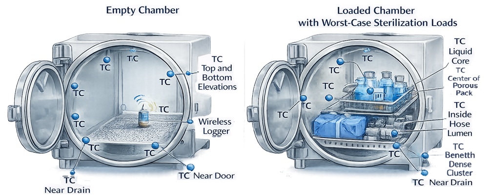
The illustration compares representative sensor placement in an empty chamber with placement around and within a worst-case loaded chamber.
The illustrated locations are examples, not mandatory universal locations. Actual placement must be based on sterilizer design, cycle type, load development, heat-transfer paths, air-removal challenges, condensate behavior, and study history.
A sensor shown in the center of a liquid container represents a candidate product location. The actual liquid cold zone must be established scientifically and may not remain at the geometric center.
Temperature-Measurement Technologies
Common mapping technologies include:
- Thermocouples
- Resistance temperature detectors
- Wired temperature probes
- Wireless high-temperature data loggers
- Specialized product-penetration probes
Selection should consider:
- Required temperature range
- Accuracy
- Resolution
- Response time
- Measurement uncertainty
- Sensor dimensions
- Thermal mass
- Sampling interval
- Environmental resistance
- Steam and pressure compatibility
- Ability to fit the target location
- Ability to retain secure placement
- Data-storage capacity
- Clock stability
- Battery performance
- Calibration capability
- Compatibility with the data-acquisition system
Thermocouples
Thermocouples are frequently used because they are small, flexible, responsive, and compatible with multichannel validation systems.
Their use requires control of:
- Wire type
- Junction construction
- Extension and connector materials
- Channel assignment
- Insulation condition
- Moisture intrusion
- Electrical noise
- Reference-junction compensation
- Wire routing
- Junction location
- Secure attachment
- Calibration or verification results
The measured temperature is associated with the sensing junction, not the entire wire. The location of that junction must therefore be known and controlled.
Resistance Temperature Detectors
Resistance temperature detectors can provide high accuracy and stability but may have greater mass and slower response than fine-wire thermocouples.
Their suitability depends on:
- Probe diameter
- Sheath construction
- Insertion depth
- Response characteristics
- Available space
- Required accuracy
- Potential effect on the load
- Ability to install without creating an artificial heat-transfer path
Wireless Data Loggers
Wireless or self-contained data loggers can reduce the need to route wires through chamber penetrations.
They should be evaluated for:
- Temperature and pressure rating
- Accuracy across the study range
- Response time
- Thermal mass
- Battery condition
- Memory capacity
- Sampling interval
- Time synchronization
- Clock drift
- Software and firmware control
- Data security
- Calibration
- Download completeness
- Suitability of the protective enclosure
A wireless logger that is too large for the intended target can alter the local load configuration, restrict steam access, or fail to represent the actual product location.
Validation Data-Acquisition System
The data-acquisition system should be suitable for the intended mapping study and generate complete, accurate, attributable, and reviewable records.
Controls should address:
- System identification
- Approved software and firmware versions
- Channel configuration
- Sensor-to-channel assignment
- Units of measure
- Sampling interval
- Date and time
- Time synchronization
- User access
- Recipe or test configuration
- Calculation settings
- Data storage
- Backup
- Export
- Audit trail where applicable
- Report generation
- Raw-data retention
- Protection against unauthorized alteration
Before execution, the study team should verify:
- Correct channel identification
- Correct units
- Correct sample rate
- Plausible ambient readings
- Required sensor response
- Adequate memory
- Adequate battery capacity where applicable
- Correct calculation constants
- Correct time and date
- Communication with all sensors
- Availability of required storage space
Automated calculations should be verified before reliance on their results. A software-generated F₀ value is not reliable merely because it appears on a validated report template; the input data, reference temperature, z-value, integration interval, and analysis boundaries must be correct.
Calibration and Measurement Suitability
Mapping sensors, channels, reference standards, and associated measurement equipment should be calibrated or verified across the range relevant to the study.
Controls should address:
- Unique instrument identification
- Calibration status
- Calibration range
- Calibration points
- Accuracy
- Resolution
- Measurement uncertainty
- Reference standards
- Metrological traceability
- As-found results
- Adjustment or repair
- As-left results
- Acceptance limits
- Calibration date
- Next due date
- Environmental conditions where relevant
Calibration points should bracket or otherwise adequately cover the temperatures used to make acceptance decisions. A calibration performed only at ambient temperature does not establish suitability for a steam-sterilization exposure range.
Pre-study and post-study verification may be used to demonstrate that sensors remained within defined limits during execution. The procedure should specify:
- Verification temperature or temperatures
- Stabilization requirements
- Reference equipment
- Permitted error
- Handling of failed sensors
- Assessment of potentially affected study data
A failed post-study verification does not automatically invalidate every study result, but it requires investigation of:
- Error magnitude
- Error direction
- Affected temperature range
- Sensor data during the cycle
- Proximity of results to acceptance limits
- Whether the sensor controlled a critical conclusion
- Availability of independent or redundant evidence
Calibration and verification requirements should be consistent with the site’s GMP Calibration Program and Metrology Control.
Probe Attachment and Insertion
Poor probe installation can create misleading results even when the sensor and data-acquisition system are properly calibrated.
The sensing junction or probe tip should remain at the intended location throughout the cycle.
Attachment methods may include:
- High-temperature tape
- Stainless-steel wire
- Approved clamps
- Defined sanitary fittings
- Compression fittings
- Feedthrough assemblies
- Purpose-designed holders
- Approved insertion ports
- Qualified thermowells where representative
The selected method should not:
- Block steam contact
- Create an unintended air pocket
- Prevent condensate drainage
- Compress a porous pack unrepresentatively
- Damage packaging
- Create a major conductive heat path
- Contact a hotter chamber wall unintentionally
- Allow the sensor to move
- Compromise the sterile barrier
- Create an unacceptable leak path
- Alter the normal assembly state
Direct attachment to metal can cause the sensor to respond partly to conduction through the metal rather than to the intended local environment. This may be correct when the surface itself is the sterilization target, but it may be incorrect when the objective is to measure surrounding chamber temperature.
For internal equipment locations, the protocol should define:
- Entry point
- Insertion depth
- Probe-tip location
- Seal or fitting
- Orientation
- Distance from metal surfaces
- Relationship to condensate
- Method used to verify placement after the cycle
Retained Probe-Placement Photographs
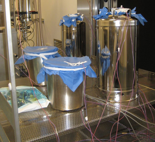
The photograph shows multiple stainless-steel vessels instrumented for a loaded heat-penetration study. It demonstrates the practical need to control vessel identification, probe location, wire routing, coverings, assembly state, and load arrangement.
The photograph shows multiple stainless-steel vessels instrumented for a loaded heat-penetration study. It demonstrates the practical need to control vessel identification, probe location, wire routing, coverings, assembly state, and load arrangement.
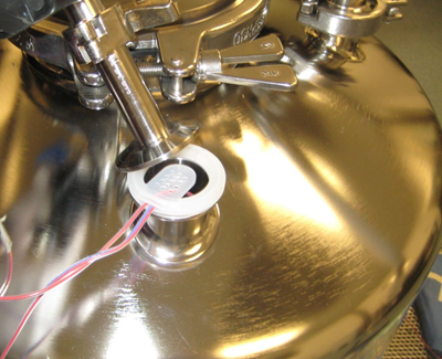
The close-up shows temperature-sensor insertion through a sanitary opening. The study record should define the sensing-junction location inside the vessel, not merely show that wires entered through the port.
Neither photograph proves that the illustrated placement was scientifically correct for another load. The images demonstrate installation practice; the placement rationale must come from the applicable load-development and mapping protocol.
Wire Routing and Chamber Penetrations
Wired sensors should be routed to minimize measurement disturbance and equipment risk.
The setup should prevent:
- Pinched or severed wires
- Door-gasket damage
- Chamber leakage
- Condensate paths along wires
- Contact with heating elements or hot walls
- Movement of load items
- Trip or handling hazards
- Channel misidentification
- Sensor-junction displacement
- Interference with drain screens, carts, or doors
When wires pass through a chamber penetration, the feedthrough should be suitable for the cycle pressure, temperature, and vacuum conditions.
Routing multiple wires through one load pathway can create an artificial steam or air path. This effect should be considered for porous packs, lumens, bags, closures, and sealed assemblies.
Time Synchronization and Sampling Interval
Temperature, pressure, control-system, BI, and data-logger records should be aligned to a common time basis or reconciled through a documented offset. Time synchronization should address:
- Validation data-acquisition system
- Sterilizer control system
- Independent pressure recorder
- Wireless loggers
- Supporting utility records
- Operator observations
- BI exposure and retrieval records
A mismatch of even one or two minutes can materially affect interpretation of exposure start, equilibration time, short temperature excursions, and F₀.
The sampling interval should be short enough to characterize:
- Vacuum and steam pulses
- Heating rate
- Exposure start
- Temperature fluctuations
- Short excursions
- Exhaust
- Cooling
- Calculated lethality
A longer sampling interval can miss brief but relevant process behavior. An unnecessarily short interval can generate excessive data without improving the conclusion. The selected interval should be justified for the cycle dynamics and calculation method.
Determining the Exposure Phase
The study must define when the exposure phase begins and ends. Possible exposure-start logic may be based on:
- Chamber-control sensor reaching its setpoint
- Drain sensor reaching a defined temperature
- Independent monitoring sensor reaching a defined condition
- All specified chamber sensors reaching a minimum temperature
- Defined load sensors reaching a minimum condition
- Completion of an equilibration criterion
- A combination of time, temperature, and control-state conditions
The sterilizer’s programmed exposure start should be compared with the independent mapping data.
A control-system status such as “exposure” does not establish that every required load location reached the defined condition. The study should determine whether the approved exposure-start logic provides adequate margin for the actual load.
The analysis should clearly distinguish:
- Conditioning
- Heating
- Equilibration
- Exposure
- Exhaust
- Cooling
- Drying
F₀ may accumulate outside the programmed exposure phase, but that does not automatically permit a cycle to violate required exposure-temperature or exposure-time criteria.
Equilibrium and Equilibration
The terms equilibrium and equilibration should be defined in the protocol rather than used generically.
Chamber Equilibrium
Chamber equilibrium may describe the point at which specified chamber-space sensors have reached the required temperature condition and their temperature spread is within a defined limit. Possible elements include:
- All required sensors above a minimum temperature
- Maximum difference between specified sensors
- Maximum time allowed to reach the condition
- Required stability period
- Exclusion or special treatment of the drain sensor where justified
- Relationship to programmed exposure start
Load Equilibration
Load equilibration describes the relationship between chamber conditions and the response of the defined load target.
A dense pack, heavy equipment assembly, filter housing, or liquid product may continue heating after the chamber has reached equilibrium.
The protocol should not apply an empty-chamber equilibrium criterion automatically to penetration sensors. Different load types can require different heating and lethality evaluations.
There is no universal equilibrium time appropriate for every sterilizer and load. The permitted time should be based on the developed cycle, equipment capability, load requirements, and approved procedure.
Cold Location and Slowest-Heating Location
“Cold spot” is widely used but can conceal several different concepts.
| Term | Meaning |
| Lowest-temperature chamber location | Chamber-space sensor reporting the lowest temperature during a defined analysis period |
| Persistent chamber cold location | Chamber location repeatedly demonstrating lower temperature behavior across comparable runs |
| Slowest-heating load location | Load sensor taking the longest time to reach a defined temperature |
| Lowest-lethality location | Sensor location with the lowest calculated F₀ or other applicable lethality measure |
| Air-removal challenge location | Location where residual air may interfere with steam contact |
| Maximum-exposure location | Location receiving the highest relevant thermal exposure |
These locations may not be identical.
Cold-location determination should consider:
- Entire temperature profile
- Exposure-phase average
- Minimum temperature
- Time to reach the minimum condition
- Duration below the required condition
- Calculated F₀
- Run-to-run consistency
- Sensor uncertainty
- Sensor position
- Evidence of air retention
- Condensate behavior
- Load configuration
- BI results
- Control and pressure data
A single instantaneous low reading should be investigated before it is declared the process cold spot. Potential causes include:
- Actual process behavior
- Sensor movement
- Moisture intrusion
- Electrical noise
- Intermittent connection
- Contact with a cold surface
- Incorrect channel assignment
- Data-acquisition error
The qualification conclusion should identify whether a consistent limiting location was established and how it relates to routine control and future requalification.
F₀ Calculation
F₀ expresses the accumulated moist-heat lethality of a temperature profile as the equivalent exposure time, in minutes, at a reference temperature of 121.1°C.
The relative lethality rate at any measured temperature is calculated as:
L = 10^((T − 121.1) / z)
where:
- L is the relative lethality rate at the measured temperature.
- T is the measured temperature in °C.
- 121.1°C is the reference temperature for F₀.
- z is the temperature change required to change the microbial D-value by a factor of ten.
- A z-value of 10°C is conventionally used for F₀ unless another value is scientifically justified.
At 121.1°C, the lethality rate equals 1.0. One minute of exposure at this temperature therefore contributes one minute of F₀.
The total F₀ is obtained by integrating the lethality rate over the selected time interval:
F₀ = ∫ 10^((T(t) − 121.1) / z) dt
For temperature data recorded at discrete time points, numerical integration is required. The trapezoidal method calculates the lethality contributed between each pair of consecutive readings:
F₀ = Σ [((Lᵢ + Lᵢ₊₁) ÷ 2) × (tᵢ₊₁ − tᵢ)]
where:
- Lᵢ is the lethality rate calculated from temperature reading Tᵢ.
- Lᵢ₊₁ is the lethality rate calculated from the next temperature reading Tᵢ₊₁.
- tᵢ₊₁ − tᵢ is the elapsed time between the readings, expressed in minutes.
- F₀ is expressed as equivalent minutes at 121.1°C for the selected z-value.
The trapezoidal method assumes that the lethality rate changes linearly between two consecutive readings. It generally provides a better numerical approximation during changing temperatures than assigning one recorded value to the entire interval. Another defined integration method may be used when it is scientifically justified, consistently applied, and verified within the approved calculation system.
The following reference points demonstrate the relationship between temperature and lethality when z = 10°C:
| Measured temperature | Relative lethality rate | F₀ contributed during one minute |
|---|---|---|
| 111.1°C | 0.1 | 0.1 minute |
| 121.1°C | 1.0 | 1.0 minute |
| 131.1°C | 10.0 | 10.0 minutes |
For example, consider two consecutive temperature readings of 120.1°C and 121.1°C recorded one minute apart.
The lethality rate for the first reading is:
L₁ = 10^((120.1 − 121.1) / 10) = 0.794
The lethality rate for the second reading is:
L₂ = 10^((121.1 − 121.1) / 10) = 1.000
Using trapezoidal integration, the F₀ contributed during that one-minute interval is:
Incremental F₀ = ((0.794 + 1.000) ÷ 2) × 1
Incremental F₀ = 0.897 minute
This calculation is repeated for every consecutive pair of readings within the defined integration period. The incremental values are then added to determine the cumulative F₀ for that sensor location.
The calculation procedure should define:
- Sensor identification and measurement location
- Reference temperature
- Applied z-value
- Temperature units
- Time units
- Sampling interval
- Numerical integration method
- Calculation start and end points
- Any minimum-temperature cutoff used for integration
- Treatment of missing, invalid, or excluded data
- Software, spreadsheet, or calculation-system version
- Calculation precision and rounding rules
- Independent verification requirements
If a minimum-temperature cutoff is used, it should be predefined and scientifically justified. Lethality accumulated below the cutoff must not be silently excluded or included inconsistently between studies.
F₀ should be calculated from the temperature history at each relevant load- or product-penetration location. A calculation based only on the chamber-control sensor, chamber drain sensor, or pressure record does not establish the lethality delivered throughout the load.
A satisfactory F₀ result does not independently demonstrate:
- Adequate air removal
- Saturated-steam contact at the sterilization target
- Compliance with a specified minimum exposure temperature or time
- Correct load configuration
- Acceptable biological-indicator results
- Package or sterile-barrier integrity
- Acceptable product quality
- Acceptable maximum thermal exposure
- Successful completion of every required cycle phase
Cumulative F₀ may support evaluation of a temperature excursion, but it should not automatically override a predefined physical acceptance criterion. If the approved protocol requires every specified sensor to remain at or above a defined temperature for a defined duration, failure to meet that requirement remains a deviation even when the calculated F₀ exceeds the minimum lethality requirement. The required lethality should be linked to the approved microbiological strategy, including the required sterility assurance level, bioburden information, microbial resistance, product requirements, and cycle-development approach.
Temperature–Pressure Evaluation
For saturated-steam cycles, chamber temperature may be compared with the saturation temperature corresponding to the measured absolute pressure.
The comparison can help identify:
- Residual air
- Non-condensable gases
- Superheat
- Sensor disagreement
- Pressure-conversion errors
- Abnormal steam conditions
- Instrument calibration problems
The assessment must account for:
- Absolute versus gauge pressure
- Local atmospheric pressure
- Instrument accuracy
- Measurement uncertainty
- Time synchronization
- Sensor location
- Steam–air mixtures
- Intended cycle type
A temperature–pressure relationship consistent with saturated steam does not prove that steam contacted every load location. Pressure is a chamber-level measurement and does not replace distributed temperature or penetration evidence.
Acceptance Criteria
Acceptance criteria should be established before execution and should cover more than minimum F₀.
Equipment and Cycle Execution
Criteria may address:
- Correct equipment
- Approved recipe
- Correct cycle version
- Correct load
- Correct item quantities and orientations
- Completed cycle phases
- Acceptable leak and air-removal tests
- No unexplained alarms
- Complete cycle record
- Acceptable utility conditions
Sensor and Data Validity
Criteria may address:
- Required sensors present
- Acceptable pre-study verification
- Acceptable post-study verification
- Correct channel assignment
- Correct location
- Secure placement
- Complete data
- Acceptable time synchronization
- No unexplained data gaps
- Acceptable data-acquisition-system status
Empty-Chamber and Loaded Distribution
Criteria may address:
- All required chamber sensors reaching a minimum temperature
- Maximum temperature
- Permitted temperature range
- Maximum sensor-to-sensor spread
- Equilibrium time
- Exposure stability
- Drain behavior
- Agreement with control and monitoring sensors
- Repeatability across runs
Heat Penetration and Lethality
Criteria may address:
- Minimum temperature at specified load locations
- Maximum heating or equilibration time
- Minimum exposure duration
- Minimum F₀
- Maximum F₀ or thermal exposure where applicable
- Acceptable BI results
- Product quality
- Package integrity
- Dryness
- Container or closure condition
- Repeatability
No universal distribution range, equilibrium time, or F₀ target applies to every steam sterilization process. The protocol should use criteria appropriate to the equipment, cycle, load, product, and sterilization strategy.
Cumulative lethality may support assessment of a transient temperature excursion, but it should not automatically override a predefined physical criterion. If the protocol requires every penetration sensor to remain above a specified temperature for a defined time, failure of that requirement is a deviation even when the calculated F₀ remains high.
Maximum Thermal Exposure
Mapping should evaluate both insufficient and excessive exposure. Potential adverse effects of excessive temperature or lethality include:
- Product degradation
- Container deformation
- Closure movement
- Seal damage
- Filter damage
- Material aging
- Loss of component function
- Excessive drying
- Package brittleness
- Changed solution concentration
- Extended cooling time
The lowest-lethality location and maximum-exposure location may occur in different loads or different positions.
For liquid cycles:
- The maximum load or largest fill may challenge minimum heat penetration.
- The minimum load or smallest fill may heat faster and receive greater exposure.
- Cooling behavior may create separate container-pressure and product-quality challenges.
Qualification should therefore evaluate the operating envelope defined during development rather than only the condition expected to produce the lowest F₀.
Biological Indicators and Physical Mapping
Temperature mapping and biological-indicator studies provide complementary evidence. Physical measurements establish:
- Actual temperature history
- Heating and cooling response
- Chamber distribution
- Load penetration
- Exposure time
- Calculated lethality
- Process reproducibility
Biological indicators provide:
- A defined microbiological challenge
- Known or characterized resistance
- Evidence from selected difficult-to-sterilize locations
- Correlation with the physical process where appropriately designed
BI placement should consider:
- Lowest-lethality locations
- Air-removal challenges
- Restricted steam pathways
- Porous or wrapped configurations
- Internal equipment surfaces
- Lumens and hoses
- Product-specific requirements
- Development-study findings
A negative BI does not compensate for unacceptable physical data. Conversely, acceptable physical data do not eliminate the need for microbiological evidence where the approved validation strategy requires it.
Detailed BI selection, resistance, placement, recovery, controls, and interpretation are addressed in Biological Indicators for Sterilization Validation.
Repeatability and Number of Runs
Mapping should demonstrate that the defined process is reproducible, not merely capable of passing once. The protocol should define:
- Number of required runs
- Whether runs must be consecutive
- Permitted time between runs
- Required setup repetition
- Reloading requirements
- Operator involvement
- Load preparation
- Sensor relocation or repeated placement
- Acceptance of each individual run
- Acceptance across the complete series
Repeatability evaluation should compare:
- Heating profiles
- Exposure-start timing
- Equilibrium or equilibration time
- Chamber distribution
- Slowest-heating location
- Lowest F₀
- Maximum exposure
- Drain response
- Cycle duration
- Pressure behavior
- BI results
- Cooling and drying
- Alarms or interventions
Three consecutive successful qualification runs are used in many validation programs, but this should not be presented as a universal regulatory number for every study. The required number should be defined by the approved qualification strategy, applicable procedure, risk, process variability, and regulatory commitments.
A failed run should not be removed and replaced without investigation. Additional successful runs do not erase the failed result.
Sensor Failures and Missing Data
A failed or questionable sensor requires documented assessment. Potential problems include:
- Open circuit
- Short circuit
- Moisture intrusion
- Electrical noise
- Implausible spike
- Flat-line response
- Data gap
- Loss of communication
- Battery depletion
- Sensor displacement
- Incorrect channel assignment
- Failed calibration or post-use verification
The assessment should determine:
- Whether the result reflects the process or the measurement system
- Whether the sensor location was critical
- Whether predefined minimum sensor coverage remained available
- Whether adjacent or redundant sensors provide relevant evidence
- Whether the cold-location conclusion remains supportable
- Whether the F₀ conclusion remains supportable
- Whether BI evidence is affected
- Whether the run remains valid
- Whether repeat testing is required
A failed sensor should not automatically be deleted from the dataset. Original data and the documented evaluation should remain part of the study record.
Acceptance of a run with a failed sensor requires more than stating that other sensors passed. The assessment must demonstrate that the failed channel did not remove evidence necessary to evaluate the intended study objective.
Deviations and Unexpected Results
Potential mapping deviations include:
- Incorrect load configuration
- Wrong recipe
- Incorrect sensor location
- Sensor displacement
- Failed calibration or verification
- Missing channel
- Incomplete data
- Time-synchronization error
- Cycle alarm
- Temperature below a required limit
- Excessive equilibrium time
- Inadequate F₀
- Excessive thermal exposure
- Positive BI
- Wet load
- Package damage
- Container breakage
- Unexpected cold location
- Failure to reproduce previous performance
The investigation should evaluate:
- What occurred
- When it occurred
- Which locations were affected
- Whether the event was process-related or measurement-related
- Effect on minimum lethality
- Effect on maximum exposure
- Effect on product or package
- Effect on other study runs
- Effect on previous qualification conclusions
- Corrective action
- Need for development reassessment
- Need for repeat testing
Repeat testing should use an approved strategy. A failed cycle should not be repeated merely to obtain a passing result. When a study identifies a new slowest-heating or lowest-lethality location, the assessment should determine whether:
- The location should be added to future studies
- BI placement should change
- Load configuration should change
- The recipe requires adjustment
- Previous qualification evidence remains adequate
- Routine monitoring should be modified
- Broader requalification is required
Data Review and Reporting
The final report should demonstrate how the raw evidence supports the conclusion. The report should include:
- Study objective and scope
- Equipment and cycle identification
- Recipe version
- Load identification
- Load diagram and photographs
- Sensor list
- Sensor-location diagram
- Placement rationale
- Calibration and verification results
- Data-acquisition-system identification
- Sampling interval
- Time-synchronization method
- Raw-data references
- Cycle records
- Temperature profiles
- Pressure profiles
- Distribution summaries
- Penetration summaries
- Equilibrium or equilibration results
- Cold-location evaluation
- F₀ results by relevant sensor
- Maximum-exposure results
- BI locations and results
- Product and package observations
- Deviations and investigations
- Run-to-run comparison
- Acceptance-criteria evaluation
- Residual risks
- Final conclusion
- Required procedural or lifecycle actions
Graphs should retain enough resolution to distinguish individual sensor traces. Overlapping traces should not obscure adverse readings.
Summary tables should not replace raw data. The complete study record should preserve:
- Original electronic files
- Unmodified sensor data
- Sterilizer cycle records
- Data-acquisition configuration
- Calculation records
- Audit-trail information where applicable
- Calibration records
- Load photographs
- Placement diagrams
- Operator observations
- BI records
- Deviations
- Approved report
Manual exclusion, smoothing, resampling, or correction of data should be controlled, scientifically justified, traceable, and reviewable.
Relationship to Qualification
Temperature mapping is a major part of steam sterilization qualification, but it does not constitute the complete qualification program. Mapping evidence supports:
- Empty-chamber thermal evaluation
- Loaded chamber evaluation
- Heat-penetration confirmation
- Minimum and maximum load coverage
- Operating-range evaluation
- Lethality demonstration
- BI placement
- Cycle repeatability
- Product and package exposure assessment
- Routine load controls
The broader Steam Sterilization Qualification Lifecycle should also address:
- Equipment installation
- Utilities
- Instrumentation
- Calibration
- Control-system functions
- Recipe security
- Alarms and interlocks
- Air removal
- Chamber leakage
- Steam quality where applicable
- Cycle-record generation
- Backup and recovery where applicable
- Procedures
- Training
- Deviations
- Release
Empty-chamber distribution is commonly associated with equipment operational qualification, while loaded heat penetration is commonly associated with performance qualification. The site lifecycle may organize these activities differently, but their technical purposes should remain explicit.
Routine Control and Requalification
Mapping conclusions should be transferred into routine controls. These may include:
- Approved load diagrams
- Load-family boundaries
- Minimum and maximum quantities
- Item orientation
- Packaging requirements
- Recipe identification
- Required exposure parameters
- Alarm and abort conditions
- Control and monitoring sensors
- Routine cycle-record review
- Product or load release requirements
- Maintenance restrictions
- Calibration requirements
- Requalification locations
- Periodic-review inputs
Reassessment may be required after changes to:
- Chamber configuration
- Door seals
- Steam inlet
- Drain
- Steam traps
- Venting
- Vacuum system
- Jacket
- Chamber-control sensor
- Cycle recipe
- Exposure-start logic
- Software
- Data-recording system
- Load item
- Load quantity
- Packaging
- Orientation
- Cart, rack, tray, or basket
- Product formulation
- Fill volume
- Container or closure
- Steam supply
- Cooling system
- Sensor-placement strategy
- BI strategy
Event-driven and periodic decisions are addressed in Requalification and Continued Verification.
Regulatory and Standards Context
For US drug manufacturing, 21 CFR 211.113(b) requires validation of sterilization processes used for sterile drug products.
FDA’s Submission Documentation for Sterilization Process Validation describes sterilization-process information supporting applications for human and veterinary drug products.
USP chapters relevant to mapping and moist-heat validation include:
- USP
<1211>Sterility Assurance - USP
<1229>Sterilization of Compendial Articles - USP
<1229.1>Steam Sterilization by Direct Contact - USP
<1229.2>Moist Heat Sterilization of Aqueous Liquids - USP
<1229.5>Biological Indicators for Sterilization - USP
<1229.9>Physicochemical Integrators and Indicators for Sterilization - USP
<1229.13>Sterilization-in-Place
Cite the USP chapter numbers without adding paywalled USP links.
ISO 17665:2024 specifies requirements for development, validation, and routine control of moist-heat sterilization processes for medical devices. Its formal scope is medical devices. Relevant technical principles may support pharmaceutical applications after documented applicability assessment, but the standard should not be misrepresented as a pharmaceutical-drug regulation.
The authority, scope, and applicability of these sources are addressed in Sterilization Regulations, Standards, and Validation Lifecycle.
Common Mapping Errors
Frequent errors include:
- Treating every thermal study as “temperature mapping” without defining its objective
- Treating empty-chamber distribution as proof of loaded heat penetration
- Using chamber-space sensors as substitutes for internal load sensors
- Assuming the chamber drain is always the coldest point
- Assuming the geometric center of every liquid is the cold zone
- Selecting sensor quantity without documented rationale
- Using evenly spaced sensors while ignoring specific load challenges
- Failing to distinguish chamber-space and penetration sensors
- Attaching sensors in a manner that creates conductive heating
- Failing to verify the sensing-junction location
- Allowing probes to move during the cycle
- Routing wires in a way that changes steam or air pathways
- Using sensors calibrated outside the relevant temperature range
- Failing to perform or assess post-study verification
- Ignoring measurement uncertainty near an acceptance limit
- Using data loggers whose mass changes local heat transfer
- Failing to synchronize sterilizer and validation-system clocks
- Using an inadequate sampling interval
- Starting analysis at the programmed exposure phase without checking independent data
- Applying one universal equilibrium criterion to all loads
- Declaring one transient low reading to be the process cold spot without investigation
- Calculating F₀ only at the chamber drain or control sensor
- Using chamber pressure as a substitute for distributed temperature evidence
- Treating cumulative F₀ as automatic justification for failure of a predefined temperature criterion
- Evaluating minimum lethality without evaluating maximum exposure
- Using negative BIs to override unacceptable physical data
- Deleting failed-sensor data
- Repeating a failed run without investigation
- Treating additional passing runs as cancellation of a previous failure
- Reporting only summary tables without retaining raw electronic data
- Failing to transfer mapping conclusions into load diagrams, procedures, and requalification requirements
Conclusion
Steam sterilization temperature mapping must distinguish chamber distribution from load and product penetration.
Empty-chamber heat-distribution studies determine whether the sterilizer can establish controlled thermal conditions throughout its chamber. Loaded distribution studies determine how a defined load affects those chamber conditions. Heat-penetration studies determine whether heat reaches difficult internal load or product locations and delivers the required lethality without excessive exposure.
A defensible study requires justified sensor quantity and placement, secure probe installation, suitable calibrated instruments, controlled data acquisition, synchronized records, defined exposure and equilibrium criteria, accurate F₀ calculations, predefined acceptance criteria, deviation control, and evaluation across repeated runs.
The resulting evidence should identify limiting chamber and load locations, confirm the approved operating envelope, support biological-indicator placement, and establish the sensor locations and controls needed for qualification and continued verification.