

Steam Sterilization Load and Cycle Development
Steam sterilization is validated for defined equipment, cycle recipes, load configurations, and operating ranges. Qualification of the empty chamber alone does not demonstrate that steam can reproducibly reach every critical surface or deliver the required lethality within every production load.
Load development identifies the items, arrangements, packaging conditions, orientations, and operating extremes that challenge air removal, steam contact, condensate drainage, heat penetration, and product protection. Cycle development converts this knowledge into a controlled recipe with defined conditioning, exposure, exhaust, cooling, and drying phases.
These activities must be performed together. A cycle cannot be properly developed without understanding the load, and a load cannot be qualified without a cycle designed for its actual heat-transfer and air-removal characteristics.
Purpose and Lifecycle Position
This article addresses:
- Intended-use and load-definition inputs
- Load inventories and load families
- Minimum, maximum, and intermediate loads
- Difficult-to-sterilize items and locations
- Porous loads, hard goods, equipment assemblies, and liquids
- Packaging, wrapping, closures, and orientation
- Air removal and steam penetration
- Condensate formation and drainage
- Chamber-drain considerations
- Heat-distribution and heat-penetration locations
- Biological-indicator selection and placement
- Lethality targets and microbiological strategy
- Cycle-phase and recipe development
- Operating ranges and validated limits
- Cycle optimization and robustness evaluation
- Load diagrams and configuration controls
- Transfer of the developed process into qualification
The scientific basis for saturated-steam heat transfer, cycle types, liquid processes, steam quality, and the boundary with SIP is addressed in Moist Heat Sterilization Principles and Cycle Types.
Development precedes formal qualification:
Define the process and load → identify challenges → develop the recipe → establish operating ranges → document the control strategy → transfer to qualification
Development establishes what should be qualified. Qualification demonstrates that the approved process performs reproducibly.
Development Is More Than Selecting an Exposure Time
A steam sterilization recipe includes more than a nominal exposure temperature and duration. Development must establish how the cycle will:
- Remove air
- Admit and distribute steam
- Heat the chamber and load
- Determine when exposure begins
- Maintain required exposure conditions
- Deliver the required lethality
- Remove condensate
- Control exhaust and depressurization
- Cool the load where required
- Dry porous or wrapped loads where applicable
- Protect packages, closures, filters, and materials
- Detect and respond to process failures
- Generate complete and reviewable cycle records
A long exposure phase cannot compensate automatically for trapped air, blocked steam pathways, uncontrolled condensate, an inappropriate load arrangement, container damage, or failure to reach the sterilization target.
Development Inputs
Development should begin with approved or controlled information describing the intended process. Required inputs may include:
- Sterilizer design and chamber dimensions
- Cycle types supported by the sterilizer
- Steam-entry, vent, drain, and vacuum-system configuration
- Chamber-control and monitoring sensors
- Jacket operation
- Vacuum capacity and leak-rate capability
- Steam-supply characteristics
- Load-cart, rack, tray, and basket design
- Item and material inventory
- Product and packaging specifications
- Required sterility assurance level
- Presterilization bioburden information
- Product or material heat sensitivity
- Maximum allowable thermal exposure
- Container-pressure limitations
- Dryness requirements
- Post-cycle handling and sterile-hold requirements
- Applicable regulatory commitments
- Existing development, engineering, or vendor data
Vendor cycles can provide an initial engineering basis, but they do not establish suitability for the site’s actual products, load configurations, packaging, utilities, or sterilization requirements.
Define the Intended Sterilization Application
The development record should first identify what the cycle is intended to accomplish. Applications may include:
- Sterilization of exposed hard goods
- Sterilization of wrapped equipment parts
- Sterilization of porous materials
- Sterilization of garments or textile packs
- Sterilization of stoppers or closures
- Sterilization of filters and filter housings
- Sterilization of hoses, tubing, and manifolds
- Sterilization of process vessels or removable assemblies
- Terminal sterilization of filled liquid containers
- Sterilization of laboratory media or solutions
- Preparation of components for aseptic processing
The intended use determines the applicable cycle type, load challenge, microbiological approach, operating parameters, and qualification strategy. Items that use materially different heat-transfer mechanisms should not be placed into one load family merely because they are processed in the same sterilizer.
Load Inventory and Item Characterization
Each item proposed for sterilization should be characterized before load-family decisions are made. The assessment should address:
| Characteristic | Development significance |
|---|---|
| Material of construction | Affects heating, moisture absorption, thermal compatibility, and drying |
| Mass and thermal capacity | Can affect heating lag, cooling, and total condensate generation |
| Geometry | Can create cavities, occluded surfaces, lumens, or condensate-retention points |
| Internal pathways | Affect air removal and steam penetration |
| Surface condition | Can affect wetting, drainage, or microbial challenge |
| Packaging or wrapping | Creates resistance to air removal and steam access |
| Closure condition | Determines whether steam can reach internal surfaces |
| Orientation | Affects air displacement, condensate drainage, and product movement |
| Quantity | Affects chamber loading, steam demand, and heating behavior |
| Position in the load | May affect steam access, condensate exposure, and heating |
| Product or solution volume | Affects liquid heat penetration and cooling |
| Viscosity | Affects convection and the location of the liquid cold zone |
| Heat sensitivity | Establishes maximum acceptable exposure |
| Sterile-hold function | Determines post-cycle handling and package-integrity requirements |
Open, closed, partially closed, assembled, and disassembled versions of the same component can represent different sterilization challenges.
Load Families
A load family is a controlled grouping of items or configurations that can be represented by a justified qualification challenge. Membership should be based on comparable sterilization characteristics, not merely a common department, product name, or equipment type.
Relevant family attributes include:
- Cycle type
- Air-removal requirement
- Heat-transfer path
- Material
- Porosity
- Wrapping or packaging
- Internal pathway geometry
- Load density
- Thermal mass
- Condensate behavior
- Drying requirement
- Exposure target
- Maximum allowable exposure
- Post-cycle handling requirements
Typical families may include:
Porous or Wrapped Loads
Examples include garments, textiles, wrapped trays, stopper bags, filters, and other materials that resist air removal or absorb moisture. Principal challenges include:
- Air retention
- Steam-penetration delay
- Dense or compressed locations
- Wet loads
- Drying difficulty
- Package damage
- Variation in folding or packing
Hard-Goods Loads
Examples include open stainless-steel parts, utensils, machine components, trays, and disassembled process equipment. Principal challenges include:
- Nested components
- Occluded surfaces
- Inverted cavities
- Restricted openings
- Condensate pooling
- Inadequate drainage
- Excessive load density
The term “hard goods” does not mean that every nonporous item presents the same sterilization challenge.
Tubing and Complex Assemblies
Examples include hoses, filling assemblies, manifolds, filter housings, vessels, and equipment with internal pathways. Principal challenges include:
- Long or narrow lumens
- Low points
- Closed valves or caps
- Internal air pockets
- Restricted condensate drainage
- Multiple connected volumes
- Incorrect assembly state
Liquid Loads
Examples include aqueous products, media, buffers, laboratory solutions, and other liquids in closed or vented containers. Principal challenges include:
- Slow heat penetration
- Location of the liquid cold zone
- Variation in fill volume
- Product viscosity
- Container geometry
- Boil-over
- Closure movement
- Container breakage
- Excessive product exposure
- Controlled cooling and depressurization
Mixed loads require specific assessment. Demonstrating acceptable performance for separate porous and hard-goods loads does not automatically qualify an arbitrary mixture of both.
Minimum, Maximum, and Intermediate Loads
The largest load is not automatically the only worst case.
Maximum Loads
Maximum loads may challenge:
- Air removal
- Steam circulation
- Heat penetration
- Steam-supply capacity
- Condensate removal
- Chamber heating
- Drying
- Cooling
Maximum-load definition should include more than total item count. It may also require limits for mass, density, number of trays, package dimensions, fill volume, or occupied chamber volume.
Minimum Loads
Minimum loads may challenge:
- Temperature distribution
- Control-system response
- Heating or cooling rate
- Material overheating
- Excessive delivered lethality
- Package drying or damage
- Pressure response
- Sensor representativeness
For liquid products, the minimum load may heat faster and receive greater thermal exposure, while the maximum load or largest fill volume may be slower to heat. Both ends of the operating range may therefore require evaluation.
Intermediate Loads
An intermediate load is not automatically covered merely because the minimum and maximum loads passed. Bracketing is defensible when development evidence demonstrates that:
- The relevant load variables change predictably
- No new air-removal or condensate challenge appears between the extremes
- Intermediate arrangements do not create unique geometric restrictions
- The same cycle recipe and control strategy remain applicable
- The tested extremes reasonably bound routine operation
Where these conditions are not met, representative intermediate configurations may require separate evaluation.
Identifying the Difficult-to-Sterilize Condition
Worst case means the condition most difficult for the required process outcome. It does not always mean the largest, heaviest, or most densely packed load. Different outcomes may have different worst cases:
| Development objective | Potential worst-case condition |
| Air removal | Most restrictive pathway, densest porous pack, closed cavity, longest lumen |
| Steam penetration | Tightest wrapping, densest arrangement, least accessible internal surface |
| Heat penetration | Largest fill volume, highest viscosity, greatest thermal mass |
| Condensate drainage | Lowest internal point, inverted component, poorly oriented hose or vessel |
| Drying | Most absorbent material, densest pack, maximum condensate-generating load |
| Minimum lethality | Slowest-heating or lowest-temperature load location |
| Maximum product exposure | Fastest-heating, smallest, or most exposed configuration |
| Container protection | Largest pressure differential or most pressure-sensitive package |
| Package integrity | Most heat-sensitive seal, closure, wrap, or sterile barrier |
One load configuration may not represent all of these challenges. Development may require multiple challenge loads or separate test conditions.
Load-Development Decision Framework
A practical load-development decision should proceed through the following steps:
| Step | Decision | Required output |
| 1 | What items and products require sterilization? | Controlled item and configuration inventory |
| 2 | How does steam or heat reach each target? | Defined heat-transfer and air-removal pathways |
| 3 | Which items behave similarly? | Justified load families |
| 4 | What variables create the greatest challenge? | Worst-case assessment |
| 5 | Which minimum, maximum, or special configurations require study? | Development-load matrix |
| 6 | Where should temperature sensors and BIs be placed? | Location rationale and study diagrams |
| 7 | What recipe and operating range control the identified risks? | Proposed cycle recipe and parameters |
| 8 | Has the process been optimized and shown to be robust? | Approved development results |
| 9 | What must be confirmed during qualification? | Qualification-transfer package |
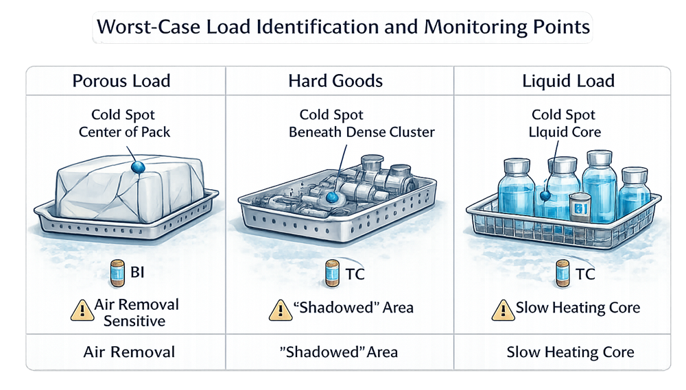
The marked locations in the illustration are representative development hypotheses. The center of a porous pack, an area beneath a dense component arrangement, or a liquid-container cold zone may be challenging, but the actual lowest-lethality location must be established through development data.
Packaging, Wrapping, and Closures
Packaging can protect sterilized items after processing, but it can also resist air removal, steam penetration, condensate removal, and drying.
Development should evaluate:
- Wrap material
- Number of wrap layers
- Folding pattern
- Package dimensions
- Package density
- Permeability
- Pouch or bag design
- Closure method
- Filter or vent configuration
- Container material
- Seal strength
- Package orientation
- Maximum package contents
- Post-cycle handling
- Sterile-hold duration
The most tightly wrapped or densest package may be the most difficult to sterilize, but the loosest or lightest package may be more vulnerable to damage during evacuation, exhaust, or drying.
Packaging should be evaluated for both sterilant access and maintenance of the required sterile barrier after processing.
Load Orientation and Arrangement
Orientation can materially change sterilization performance. Development should define:
- Item position
- Openings facing upward, downward, or sideways
- Valve and closure positions
- Hose routing
- Tray and basket positions
- Container spacing
- Separation between wrapped items
- Stacking restrictions
- Vessel tilt
- Filter orientation
- Drainage paths
- Relationship to chamber walls, steam entry, and drain
An acceptable orientation should support air removal, steam contact, and condensate drainage. An item that sterilizes successfully in one orientation should not automatically be approved in every orientation.
The approved configuration should be practical enough to reproduce routinely. A configuration that depends on informal operator judgment is not adequately controlled.
Air Removal and Steam Access
For direct-contact steam sterilization, air must be removed from both the chamber and the load. Load-related air-removal challenges include:
- Dense porous packs
- Narrow lumens
- Closed or restricted openings
- Nested components
- Inverted containers
- Filter housings
- Long hoses
- Valve cavities
- Equipment assemblies
- Impermeable packaging
- Excessive load density
Development may evaluate:
- Number of vacuum or pressure pulses
- Vacuum depth
- Steam-pulse pressure
- Rate of pressure change
- Hold time at pulse conditions
- Steam-flush duration
- Chamber leak performance
- Load response during conditioning
- Air-detector or process-challenge-device response
- Transition criteria before exposure
An empty-chamber air-removal test confirms an equipment function. It does not independently prove air removal from every production load.
Condensate and Drainage
Condensate is produced when saturated steam releases latent heat to cooler load surfaces. The cycle and load must allow that condensate to drain without blocking steam contact or accumulating in critical locations.
Development should examine:
- Chamber slope
- Drain condition
- Steam-trap performance
- Load-cart drainage
- Basket and tray perforation
- Component low points
- Hose routing
- Vessel orientation
- Filter-housing drainage
- Condensate quantity
- Load thermal mass
- Drying performance
- Evidence of retained water after the cycle
Excess condensate may contribute to:
- Delayed heating
- Wet loads
- Local temperature effects
- Blocked air-removal paths
- Filter wetting
- Container damage
- Corrosion
- Post-cycle handling difficulties
Chamber-Drain Location
The chamber drain is an important monitoring and development location because air and condensate commonly leave the chamber through that path. However:
- The drain is not automatically the coldest chamber location.
- The coldest chamber location is not necessarily the slowest-heating load location.
- A load may contain several locations more difficult to sterilize than the drain.
- The relationship can change with the cycle and load configuration.
Development data should establish how drain behavior relates to chamber distribution and load penetration.
Heat Distribution and Heat Penetration
Heat distribution and heat penetration serve different purposes.
| Study | Development question |
| Empty-chamber heat distribution | How does the chamber establish and control thermal conditions without a production load? |
| Loaded-chamber distribution | How does the load affect chamber-space temperature behavior? |
| Load heat penetration | Where does heat reach the sterilization target most slowly within the actual load? |
| Product heat penetration | Where is the lowest delivered lethality within a liquid, package, assembly, or product? |
Development sensor locations may include:
- Chamber drain
- Chamber corners
- Locations near doors
- Upper and lower chamber elevations
- Center of porous packs
- Dense package locations
- Internal surfaces of vessels
- Hose or lumen endpoints
- Filter housings
- Restricted cavities
- Largest liquid fill
- Scientifically predicted liquid cold zones
- Locations remote from steam entry
- Areas with known condensate-retention risk
The slowest-heating or lowest-lethality location can move when the load, orientation, fill volume, packaging, recipe, or cooling strategy changes.
Detailed study execution is addressed in Temperature Mapping and Heat Distribution.
Developing the Cycle Recipe
The cycle recipe should be based on the actual load challenge and equipment capability.
Conditioning and Air Removal
Development should establish:
- Initial chamber condition
- Jacket preheating where used
- Number and sequence of vacuum or steam pulses
- Vacuum and pressure targets
- Hold times
- Steam-admission rate
- Venting
- Transition criteria
- Maximum permitted conditioning duration
The sequence should remove air without damaging the load, packages, filters, or containers.
Heating and Equilibration
Development should determine:
- Exposure-temperature setpoint
- Heating rate
- Chamber-control method
- Maximum equilibration time
- Relationship between chamber and load temperatures
- Conditions required before exposure begins
Exposure should not begin merely because one chamber-control sensor reached its setpoint unless development demonstrates that this logic provides adequate control of the defined sterilization targets.
Exposure
Development should define:
- Exposure-temperature setpoint
- Permitted temperature range
- Minimum exposure duration
- Maximum exposure duration where applicable
- Pressure conditions
- Lethality target
- Control and monitoring sensors
- Timing logic
- Alarm and abort conditions
- Response to short excursions
- Requirements for independent records
Exhaust, Depressurization, and Cooling
Development should address:
- Exhaust rate
- Vacuum application
- Controlled pressure reduction
- Sterile-air admission
- Cooling-water operation
- Air overpressure
- Product cooling target
- Container-pressure protection
- Closure movement
- Boil-over
- Package damage
- Minimum release or handling temperature
These controls are particularly important for sealed liquids and flexible containers.
Drying
For porous and wrapped loads, development should establish:
- Drying-vacuum conditions
- Jacket temperature
- Drying duration
- Air admission
- Acceptable residual moisture
- Maximum material exposure
- Package condition after processing
Extending drying time should not be used to conceal inadequate steam quality, poor load configuration, excessive condensate, or deficient drainage.
Lethality Targets and Development Approach
The sterilization target should be defined before the final recipe is selected. The strategy may use:
- Bioburden-based development
- Overkill development
- Combined physical and microbiological evidence
- Product-specific resistance data
- Partial or fractional-cycle studies
- Full-cycle confirmation
The selected approach should consider:
- Required sterility assurance level
- Presterilization bioburden
- Microbial identity and resistance
- Biological-indicator characteristics
- Product and material compatibility
- Minimum required lethality
- Maximum acceptable exposure
- Regulatory commitments
- Routine monitoring capability
For moist-heat processes, delivered lethality may be expressed as F₀ using the defined reference temperature and z-value.
F₀ is one element of development. It does not independently demonstrate:
- Air removal
- Steam contact
- Adequate exposure at unmonitored locations
- Package integrity
- Product quality
- Correct cycle execution
- Suitability of the biological challenge
A universal F₀ target should not be assigned to every product or load without considering the microbiological strategy and product-specific requirements.
Biological-Indicator Strategy
Biological indicators provide a defined microbiological challenge at selected difficult-to-sterilize locations. Development should establish:
- Intended purpose of the BI
- Organism and strain
- Population
- D-value and applicable test conditions
- z-value where relevant
- Carrier material
- BI format
- Packaging
- Resistance under actual process conditions
- Placement
- Retrieval
- Recovery method
- Incubation conditions
- Positive controls
- Acceptance criteria
BI locations may include:
- Centers of porous packs
- Restricted internal surfaces
- Long or narrow lumens
- Filter housings
- Densely packed areas
- Locations with difficult steam access
- Scientifically justified liquid-product locations
- Process challenge devices representing actual loads
Temperature sensors and BIs may be colocated where practical, but placement must not materially change the local challenge. A bulky BI or sensor can alter packaging, steam access, or heat transfer.
The location with the lowest measured F₀ is an important BI candidate, but BI placement should also consider air-removal and steam-contact challenges that temperature data alone may not fully characterize.
For liquid products, a commercial BI placed outside the product may not represent the product environment. Product inoculation, an appropriate carrier, a process challenge device, or another qualified approach may be necessary.
Detailed BI control is addressed in Biological Indicators for Sterilization Validation.
Partial and Fractional-Cycle Studies
Partial or fractional cycles may be used during development to:
- Identify survival and inactivation behavior
- Compare candidate BI locations
- Evaluate relative load difficulty
- Confirm that the challenge is not excessively weak
- Support an overkill strategy
- Assess the relationship between physical lethality and BI response
- Optimize exposure conditions
Such studies should define which cycle phases remain unchanged and which exposure parameter is reduced.
A partial cycle is a development tool. Its results should not be interpreted as evidence that a routine production cycle may operate below the approved exposure requirements.
Operating Ranges and Validated Limits
Development should distinguish among:
| Term | Meaning |
| Setpoint | Target value used by the control system |
| Operating range | Range expected during normal controlled operation |
| Alert or alarm limit | Value that prompts notification, intervention, or cycle action |
| Acceptance criterion | Requirement used to evaluate a study or cycle |
| Validated limit | Boundary supported by qualification evidence |
| Equipment capability | Range the equipment can physically achieve, whether validated or not |
These values are not interchangeable.
Development should establish which parameters require:
- Fixed values
- Minimum limits
- Maximum limits
- Permitted ranges
- Time-at-condition requirements
- Transition criteria
- Alarm or abort logic
- Operator restrictions
Parameters may include:
- Vacuum depth
- Pulse pressure
- Number of pulses
- Conditioning duration
- Exposure temperature
- Exposure time
- Chamber pressure
- Equilibration time
- F₀
- Exhaust rate
- Cooling rate
- Overpressure
- Drying vacuum
- Drying duration
- Load temperature
- Final handling temperature
The routine operating range should remain inside the qualified limits with sufficient margin to accommodate normal variability.
Cycle Optimization
Cycle optimization seeks a reproducible balance between minimum sterilization requirements and maximum acceptable product, material, or package exposure. Increasing time or temperature may improve lethality but can also cause:
- Product degradation
- Excessive F₀
- Container deformation
- Closure movement
- Seal damage
- Material aging
- Filter damage
- Wet loads
- Extended cycle duration
- Increased energy use
- Reduced equipment availability
Reducing cycle time without understanding air removal or heat penetration can create an inadequate process.
Optimization should evaluate:
- Alternative conditioning sequences
- Pulse number and depth
- Steam-admission rate
- Exposure setpoint
- Exposure duration
- Equilibration criteria
- Exhaust rate
- Cooling profile
- Drying conditions
- Load arrangement
- Packaging configuration
- Process robustness
The selected cycle should operate reliably under expected variability without depending on excessive thermal exposure to compensate for weak load or equipment design.
Robustness and Development Challenges
Development should evaluate plausible sources of variability, including:
- Minimum and maximum loads
- Different approved load positions
- Permitted item quantities
- Packaging variability
- Fill-volume range
- Product-viscosity range
- Initial load temperature
- Utility variability
- Different operators
- Chamber loading time
- Maximum precycle hold time
- Steam-supply pressure
- Cooling-water condition
- Normal equipment-control variation
Development challenges should remain scientifically justified and safe. They should not create uncontrolled conditions that could damage the equipment or invalidate the study.
Equipment Assembly Load Example
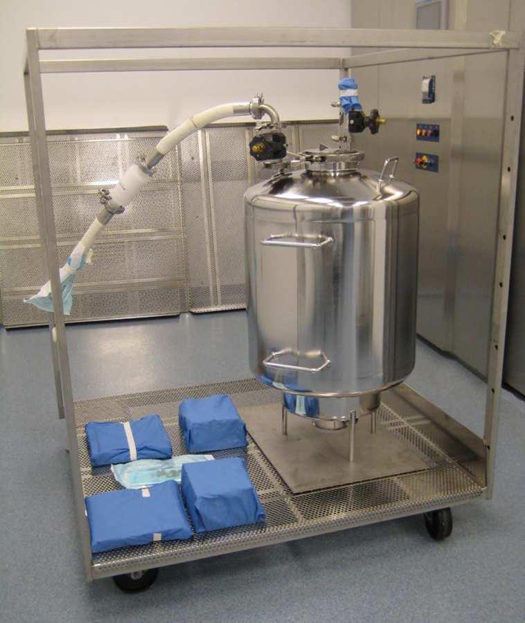
The photograph illustrates the practical complexity of an equipment load containing a vessel, connected tubing, wrapped components, multiple elevations, and potential condensate-retention points.
Development of such a load should evaluate:
- Vessel openings
- Internal surfaces
- Nozzles and branches
- Hose slope
- Hose endpoints
- Valve position
- Connection state
- Wrapped-item density
- Cart position
- Drainage
- Steam access
- Sensor and BI placement
- Reproducibility of assembly
The photograph is an example of a load requiring documented development. Its appearance alone does not demonstrate that the configuration is acceptable or qualified.
Load Diagrams and Routine Configuration Control
Each approved load configuration should be represented by a controlled diagram, photograph, matrix, or combination of these records. Documentation should define:
- Load-family name and identification
- Sterilizer and cycle recipe
- Item names and identifiers
- Minimum and maximum quantities
- Packaging or wrapping
- Assembly condition
- Valve and closure positions
- Orientation
- Tray, rack, basket, and cart positions
- Stacking restrictions
- Permitted substitutions
- Representative minimum and maximum loads
- Prohibited configurations
- Post-cycle handling requirements
The diagram should contain enough detail for trained personnel to reproduce the approved load without relying on undocumented custom or memory.
Where variability is permitted, the allowable envelope must be explicit. “Typical load” is not an adequate control description.
Development Records and Required Outputs
Development should produce a traceable technical package containing:
- Intended-use definition
- Item and load inventory
- Load-family rationale
- Product and material assessment
- Minimum, maximum, and special-load definitions
- Worst-case assessment
- Development protocol or plan
- Cycle-recipe history
- Experimental-run data
- Temperature-sensor locations
- BI locations and results
- Positive-control results
- Air-removal observations
- Condensate and drying observations
- Lethality calculations
- Product and package assessments
- Deviations and investigations
- Optimization decisions
- Operating ranges
- Proposed alarms and interlocks
- Approved load diagrams
- Residual risks
- Development report
- Qualification recommendations
Unsuccessful development runs remain part of the development history. They should not be removed merely because the final recipe passed.
Transfer to Qualification
The development-to-qualification transfer package should define exactly what formal qualification must demonstrate. It should include:
| Development output | Qualification use |
| Approved cycle recipe | Establishes the configuration to be challenged |
| Critical process parameters | Defines qualification measurements and acceptance criteria |
| Load families | Establishes qualification grouping |
| Minimum and maximum loads | Defines operating-envelope challenges |
| Worst-case rationale | Supports load and location selection |
| Sensor-location rationale | Defines heat-distribution and penetration studies |
| BI strategy | Defines microbiological challenges |
| Operating ranges and validated-limit proposals | Defines low-side, high-side, or nominal challenges |
| Alarm and interlock requirements | Defines functional testing |
| Load diagrams | Establishes reproducible qualification configurations |
| Product and package limits | Defines maximum-exposure assessments |
| Residual risks | Identifies required controls and additional testing |
Formal qualification should confirm:
- Equipment and utility readiness
- Recipe control
- Air-removal performance
- Chamber heat distribution
- Loaded heat distribution
- Load or product heat penetration
- Delivered lethality
- BI results
- Alarm and interlock performance
- Cycle reproducibility
- Minimum and maximum load coverage
- Product and package acceptability
- Complete and accurate cycle records
Detailed execution is addressed in Steam Sterilization Qualification Lifecycle.
Development runs should not automatically be counted as qualification runs. Their use as formal qualification evidence requires prior approval, suitable protocols, calibrated instruments, controlled configurations, predefined acceptance criteria, complete records, and compliance with the applicable qualification procedure.
Changes Requiring Development Reassessment
Development conclusions should be reassessed after changes to:
- Load items
- Item quantities
- Materials
- Packaging or wrapping
- Container or closure system
- Fill volume
- Product formulation or viscosity
- Orientation
- Trays, racks, baskets, or carts
- Cycle recipe
- Air-removal sequence
- Exposure parameters
- Exhaust, cooling, or drying
- Sterilizer control logic
- Steam supply
- Chamber drain or steam traps
- Vacuum system
- Chamber sensors
- Load-family boundaries
- BI or process challenge device
- Post-cycle handling
- Maximum allowable exposure
The assessment should determine whether the change requires documentation update, targeted development, qualification testing, or broader requalification.
Lifecycle decisions are addressed in Requalification and Continued Verification.
Regulatory and Standards Context
For US drug manufacturing, 21 CFR 211.113(b) requires written procedures designed to prevent microbiological contamination of sterile drug products, including validation of sterilization processes.
FDA’s Submission Documentation for Sterilization Process Validation describes sterilization-process information supporting human and veterinary drug applications.
FDA’s Aseptic Processing guidance addresses sterilization of equipment and components supporting aseptic processing and emphasizes the preference for terminal sterilization when the product and container system can withstand it.
USP chapters relevant to load and cycle development include:
- USP
<1211>Sterility Assurance - USP
<1229>Sterilization of Compendial Articles - USP
<1229.1>Steam Sterilization by Direct Contact - USP
<1229.2>Moist Heat Sterilization of Aqueous Liquids - USP
<1229.3>Monitoring of Bioburden - USP
<1229.5>Biological Indicators for Sterilization - USP
<1229.9>Physicochemical Integrators and Indicators for Sterilization
Cite the chapter numbers without adding paywalled USP links.
ISO 17665:2024 specifies requirements for development, validation, and routine control of moist-heat sterilization processes for medical devices. Its formal scope is medical devices; use in pharmaceutical applications requires documented applicability assessment.
The legal status and applicability of these sources are addressed in Sterilization Regulations, Standards, and Validation Lifecycle.
Common Development Errors
Frequent errors include:
- Treating sterilizer qualification as qualification of every load
- Developing the cycle independently of the load
- Assuming the maximum load is the only worst case
- Ignoring minimum-load behavior
- Grouping dissimilar items into one load family
- Qualifying a single “typical” load without defining permitted variability
- Assuming the chamber drain is always the coldest location
- Treating chamber distribution as proof of load penetration
- Selecting BI locations without development data
- Using a negative BI to compensate for unacceptable physical parameters
- Treating the center of every liquid container as the automatic cold zone
- Ignoring packaging, wrapping, closures, or orientation
- Failing to evaluate condensate drainage
- Increasing exposure time to compensate for inadequate air removal
- Starting exposure before the defined load conditions are achieved
- Using vendor cycle settings without site-specific development
- Failing to distinguish setpoints, operating ranges, and validated limits
- Defining minimum lethality without defining maximum acceptable exposure
- Assuming separate qualified loads justify uncontrolled mixed loads
- Counting exploratory development runs as formal qualification without justification
- Failing to transfer development decisions into controlled load diagrams and qualification protocols
Conclusion
Steam sterilization load and cycle development establishes the scientific and operational basis for qualification.
The process begins by defining the items, products, packaging, configurations, and sterilization requirements. Related items are organized into justified load families, and minimum, maximum, and special challenge conditions are identified. Development studies then determine how air is removed, how steam reaches the sterilization target, where condensate drains, where heat penetration is slowest, and where temperature sensors and biological indicators should be placed.
This evidence is used to establish a cycle recipe, operating ranges, lethality targets, alarms, load diagrams, and routine configuration controls. The final development package transfers these requirements into qualification, where the approved equipment, cycle, and load operating envelope are demonstrated to perform reproducibly.