

Electron Beam Sterilization Process and Dose Control
Electron beam sterilization uses high-energy electrons generated by an electrically powered accelerator to deliver a controlled absorbed dose to a defined product and packaging configuration. Unlike gamma irradiation, e-beam does not depend on a continuously radioactive source. The accelerator produces radiation only when energized.
E-beam is commonly used for:
- Single-use medical devices
- Laboratory and diagnostic products
- Pharmaceutical manufacturing components
- Certain packaging materials
- Low- to moderate-density cartons
- Products requiring short irradiation exposure
- High-volume products suited to continuous conveyor processing
- Products demonstrated to remain acceptable throughout the specified dose range
The main advantages are rapid dose delivery, electrical on/off control, and potentially high throughput. The principal limitation is penetration. Electrons lose energy rapidly as they pass through matter, making product density, thickness, internal geometry, orientation, and packaging configuration critical process variables.
The process must control both ends of the absorbed-dose specification: Dmin≥Dster
and: Dmax≤Dmax,acc
where:
- Dmin is the minimum absorbed dose within the product
- Dster is the substantiated sterilization dose
- Dmax is the maximum absorbed dose within the product
- Dmax,acc is the demonstrated maximum acceptable dose
E-beam sterilization of medical devices falls within ISO 11137-1:2025, which addresses radiation processes using radionuclide, electron-generator, and X-ray-generator irradiators. FDA completely recognizes this edition as consensus standard 14-611, subject to the transition information in the FDA recognition database.
ISO 11137 is written for medical devices. Its principles may support other healthcare and pharmaceutical applications, but applying e-beam to a drug, biologic, excipient, or pharmaceutical-process material requires product-specific regulatory, chemical, and quality assessment.
Dose establishment, bioburden control, performance qualification, dose audits, change control, and requalification are addressed in Radiation Sterilization Validation, Dose Establishment, and Lifecycle Control.
Electron-Beam Generation
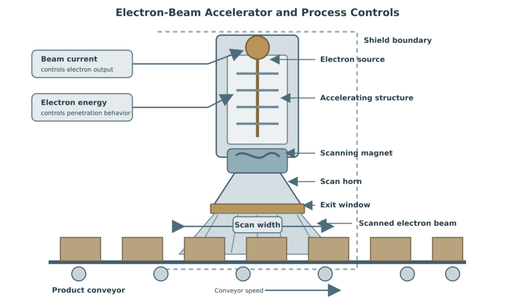
An electron accelerator produces and controls a stream of high-energy electrons.
A typical system includes:
- Electron source or electron gun
- Accelerating structure
- High-voltage or radiofrequency power system
- Vacuum system
- Beam-focusing and steering components
- Scanning magnet
- Scan horn
- Beam-exit window
- Window and accelerator cooling
- Product conveyor
- Product-positioning or turning equipment
- Shielded irradiation vault
- Safety interlocks
- Radiation-monitoring instruments
- Process controller
- Dosimetry system
- Untreated- and treated-product controls
The electron gun releases electrons into an evacuated accelerating structure. An electrical field increases their kinetic energy. Beam-control magnets focus, steer, and scan the electrons across the required treatment width.
The electrons leave the accelerator vacuum through a thin metallic exit window, commonly titanium or a titanium alloy. They then pass through the air gap or another defined path before reaching the product.
Energy is lost in:
- The exit window
- Cooling structures
- Air between the window and product
- Product packaging
- Product material
The energy reported by the accelerator control system is therefore not automatically identical to the energy reaching the product surface. Equipment characterization and dosimetry must represent the installed operating geometry.
Accelerator Technologies
Industrial electron accelerators may use several designs, including:
- Linear accelerators
- Dynamitrons
- Rhodotrons
- Transformer-based accelerators
- Direct-current accelerators
- Pulsed accelerators
- Electron-curtain systems for lower-energy applications
High-energy accelerators used for packaged healthcare products commonly operate in the several-MeV range, frequently up to approximately 10 MeV. The selected energy must correspond to the product, facility design, applicable regulatory constraints, and validated penetration requirement.
Lower-energy electron systems may be used for surface treatment, films, packaging components, or other thin products. They should not be represented as equivalent to high-energy systems used for packaged-product sterilization.
The accelerator design affects:
- Available electron energy
- Maximum beam current
- Beam power
- Pulse characteristics
- Scan width
- Scan uniformity
- Product clearance
- Cooling requirements
- Throughput
- Depth–dose distribution
- Equipment failure modes
Product Path Through the Irradiator
Product is normally transported through the beam on a controlled conveyor. Depending on the system, product may be processed using:
- A single pass under the beam
- Multiple passes
- Side-by-side conveyor lanes
- Product rotation
- Product flipping
- Separate exposure of opposite sides
- A return conveyor
- A two-accelerator arrangement
- A defined carrier or tote
- Individual cartons without a separate carrier
The approved process specification should define:
- Product identity
- Carton or package dimensions
- Product weight
- Density limits
- Internal loading pattern
- Conveyor lane
- Conveyor direction
- Product orientation
- Distance from the beam-exit window
- Conveyor speed
- Beam energy
- Beam current
- Scan width
- Number of passes
- Single- or double-sided processing
- Turning or flipping sequence
- Routine dosimeter position
- Permitted neighboring-product conditions
A product qualified in one orientation should not be rotated, inverted, or transferred to another conveyor lane without assessing dose distribution.
Electron Energy
Electron energy is normally expressed in megaelectronvolts: 1 MeV=106 eV. Energy primarily affects:
- Electron penetration
- Depth of maximum dose
- Practical product thickness
- Depth–dose curve
- Beam spreading
- Scan geometry
- Radiation generated by interactions with equipment and product
Higher electron energy generally increases penetration, but it does not eliminate density-related attenuation or guarantee an acceptable dose-uniformity ratio.
Energy that is too low may cause:
- Inadequate penetration
- An unacceptable internal minimum dose
- A steep dose gradient
- Excessive surface-to-core dose difference
An energy setting above the established range can also change:
- Maximum-dose location
- Depth of peak dose
- Dose beyond the intended product layer
- Scan width
- Shielding conditions
- Relationship between routine dosimetry and product dose
Electron energy is therefore a qualified equipment and process parameter. It should not be changed merely to increase throughput or accommodate a different product.
Beam Current and Beam Power
Beam current represents the rate at which electrical charge is carried by the electron beam. It is commonly expressed in milliamperes. For a defined energy, higher beam current provides greater beam power and generally increases the dose delivered per unit time.
Beam power can be represented as: Pb=EI
where:
- Pb is electron-beam power
- E is electron energy
- I is beam current
When energy is expressed in MeV and current in mA, their product corresponds numerically to beam power in kilowatts: 10 MeV×10 mA=100 kW
Beam current primarily influences:
- Dose rate
- Dose delivered at a defined conveyor speed
- Commercial throughput
- Thermal loading
- Exit-window loading
- Accelerator and cooling-system demand
Beam current does not independently establish penetration depth. A high-current beam at inadequate energy may deliver a high surface dose while still failing to deliver the required internal dose.
Conveyor Speed
Conveyor speed controls the time that product remains within the scanned radiation field. For an otherwise unchanged configuration:
- Decreasing conveyor speed generally increases absorbed dose.
- Increasing conveyor speed generally decreases absorbed dose.
The relationship must be established by dosimetry. It can be affected by:
- Beam-current variation
- Scan width
- Energy
- Product height
- Distance from the exit window
- Conveyor lane
- Product orientation
- Pulse characteristics
- Beam-utilization efficiency
- Product interruptions or gaps
For a fixed qualified geometry, dose delivery may be represented conceptually as: D∝vwI , where:
- D is absorbed dose at the defined reference condition
- I is beam current
- v is conveyor speed
- w is effective scan width
- The sign ∝ means “is proportional to.”
This relationship explains the primary controls but is not a product-release equation. Actual product dose depends on the validated dose map, equipment characterization, monitoring position, product configuration, and measurement uncertainty.
Some systems maintain a controlled relationship between beam current and conveyor speed. If beam current changes, the conveyor speed may be adjusted automatically to maintain the intended dose. This control function requires qualification, alarm testing, and verification of failure response.
Scan Width and Scan Uniformity
The accelerator does not normally expose a commercial carton using a stationary narrow beam. The scanning magnet sweeps the electron beam across the product path.
Scan width must:
- Cover the defined product width
- Include an established edge margin
- Remain within the qualified exit-window area
- Produce acceptable uniformity across the processing zone
- Correspond to the product height and window distance
- Remain consistent with the routine dosimetry position
Increasing scan width spreads the available beam power across a wider treatment area. If beam current and conveyor speed remain unchanged, increasing scan width can reduce dose per unit area.
Scan control includes more than a nominal width setting. Relevant characteristics may include:
- Scan frequency
- Scan amplitude
- Beam-position stability
- Beam profile
- Edge behavior
- Uniformity across the scan
- Beam centering
- Relationship between scan width and product height
- Response to loss of scanning
A loss or narrowing of scan can produce severe localized overexposure and underexposure. The system should detect unacceptable scan conditions and place affected product into a controlled status.
Beam Window and Product Geometry
The distance between the accelerator exit window and the product affects:
- Energy loss before product contact
- Beam divergence
- Effective scan width
- Surface-dose distribution
- Penetration profile
- Relationship to the qualified irradiation geometry
Product height is therefore not merely a conveyor-clearance issue. A taller or shorter package can change its distance from the exit window and its position within the radiation field.
The process specification should control:
- Maximum and minimum product height
- Product-to-window distance
- Conveyor elevation
- Package orientation
- Protrusions
- Uneven carton surfaces
- Carrier thickness
- Product movement during exposure
Electron Penetration and Depth–Dose Behavior
Electrons have mass and electrical charge. They interact strongly with matter, scatter, lose energy, and eventually stop.
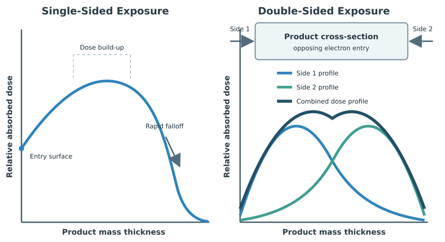
A representative depth–dose curve does not normally begin at its maximum and then decline in a simple straight line. Depending on the energy, material, geometry, and measurement conditions, the dose can build to a maximum below the surface and then decrease rapidly near the end of the electron range.
The profile may include:
- Surface-entry dose
- Dose build-up
- Maximum-dose region
- Gradual loss of electron energy
- Rapid falloff near the practical range
- A small photon background beyond the main electron range
The actual profile depends on:
- Electron energy
- Energy spread
- Material composition
- Material density
- Mass thickness
- Product geometry
- Exit-window construction
- Air gap
- Beam incidence angle
- Scattering
- Measurement method
Penetration should not be expressed as one universal number of inches. A thickness that can be treated in a low-density product may be unsuitable for the same physical thickness of a denser material.
Mass Thickness and Areal Density
Electron penetration is better evaluated through mass thickness than physical thickness alone.
Mass thickness can be expressed as: xm=ρt, where:
- xm is mass thickness, commonly expressed in g/cm2
- ρ is material density
- t is physical thickness
A low-density product can have a relatively large physical thickness but a moderate mass thickness. A thinner high-density product can present a greater penetration challenge.
This relationship is useful for initial product screening, but it does not replace dose mapping because commercial packages may contain:
- Local density concentrations
- Air gaps
- Nested components
- Metal parts
- Liquids or gels
- Bundled tubing
- Multiple packaging layers
- Angled surfaces
- Shielded regions
- Nonuniform unit distribution
Product Density and Configuration
Average packaged-product density may be calculated as: ρbulk=Vm, where:
- m is packaged-product mass
- V is the external package volume
Bulk density is useful for preliminary categorization and routine configuration control. It does not describe local density distribution.
Two cartons having the same external dimensions and average density may behave differently when:
- One contains evenly distributed components.
- One concentrates dense components near its center.
- One contains large internal voids.
- One contains metal or liquid-filled assemblies.
- One contains nested products.
- One uses a different internal divider.
- One allows components to shift during transport.
The validated configuration may need to define:
- Product count
- Component arrangement
- Unit orientation
- Package dimensions
- Carton weight range
- Bulk-density range
- Local density restrictions
- Divider and insert design
- Permitted voids
- Packaging materials
- Product movement restrictions
- Partial-carton configuration
Weight checks can detect some loading errors but cannot establish dose equivalence by themselves.
Single-Sided Exposure
In single-sided processing, electrons enter principally from one direction. This approach may be suitable when:
- Product mass thickness is sufficiently low
- The minimum dose can be achieved at the deepest required location
- The entry-side maximum dose remains acceptable
- Dose uniformity remains within the product’s allowable range
- Product orientation is reliably controlled
Single-sided exposure can produce a substantial difference between the entry-side and exit-side doses. Whether this difference is acceptable must be established by mapping.
Double-Sided Exposure
Double-sided exposure can extend the treatable mass thickness and improve dose distribution. It may be achieved by:
- Flipping the product between passes
- Rotating the product
- Using separate upper and lower accelerators
- Using opposing beams
- Processing the product through a controlled return path
The second exposure does not simply “fill in” the first exposure uniformly. The final distribution is the sum of two configuration-dependent depth–dose profiles. Double-sided processing requires control of:
- First-side orientation
- Second-side orientation
- Flipping or rotation mechanism
- Sequence of exposures
- Dose contribution from each side
- Time between exposures, where relevant
- Product tracking
- Response to incomplete second exposure
- Cumulative maximum dose
- Routine dosimeter strategy
If one side receives a complete exposure and the second side is missed, the product cannot be accepted merely because one conveyor pass was completed. Conversely, repeating both sides after an interruption may exceed the maximum acceptable dose.
Dose Distribution and Dose Mapping
Dose distribution in an e-beam process depends on the complete relationship among:
- Accelerator
- Electron energy
- Beam current
- Scan width
- Scan uniformity
- Conveyor speed
- Product-to-window distance
- Conveyor lane
- Product height
- Product density
- Internal geometry
- Package orientation
- Number and direction of exposures
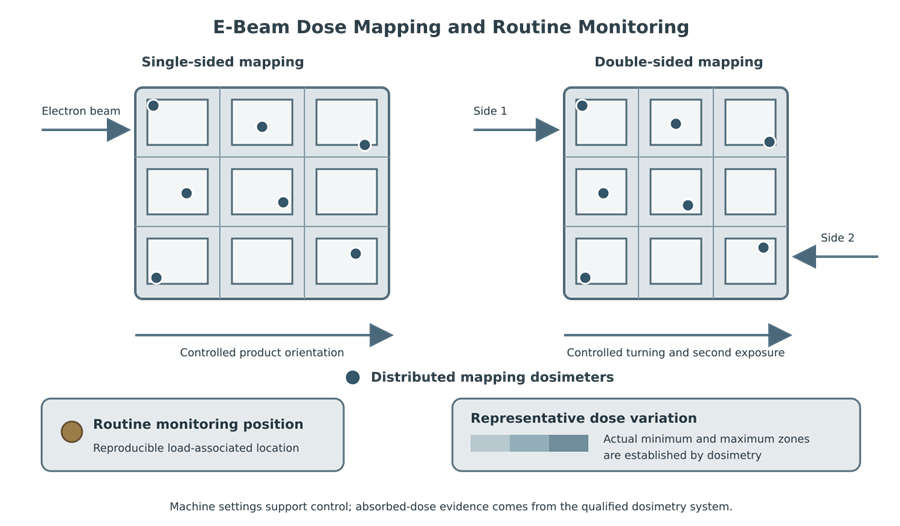
Dose mapping is used to determine:
- Minimum-dose zones
- Maximum-dose zones
- Depth–dose behavior
- Dose variation across the scan
- Leading- and trailing-edge effects
- Lane-to-lane variation
- Dose variation among cartons
- Effect of product orientation
- Effect of double-sided processing
- Relationship between routine monitoring dose and product-dose extremes
- Dose uniformity ratio
The minimum-dose location should not be assumed to be the geometric center. The maximum-dose location should not automatically be assigned to the top surface or leading edge. The actual locations must be established by dosimetry.
The dose uniformity ratio is: DUR=DminDmax
DUR applies to the mapped accelerator, product, packaging, orientation, conveyor path, and exposure sequence. It is not a universal characteristic of e-beam equipment.
Dosimetry
Dosimetry provides the quantitative evidence of absorbed-dose delivery. Machine parameters support process control but do not replace dose measurement. An e-beam dosimetry system may include:
- Radiochromic film
- Alanine dosimeters
- Other dosimeters suitable for the energy, dose range, and dose rate
- Dosimeter packaging or holder
- Defined placement procedure
- Measurement instrumentation
- Calibration
- Response calculation
- Environmental corrections
- Measurement uncertainty
- Data review
- Traceability
- Record retention
Thin-film dosimeters are particularly useful for characterizing:
- Depth–dose profiles
- Beam uniformity
- Scan width
- Edge effects
- Local dose gradients
- Dose distributions in thin or complex configurations
Dosimetry must be appropriate for the applicable:
- Electron energy
- Dose range
- Dose rate
- Pulse structure
- Product temperature
- Irradiation geometry
- Time between irradiation and reading
- Measurement instrument
ISO 11137-3:2017 provides guidance on dosimetric aspects of radiation sterilization. ASTM 51649-22e1 addresses electron-beam radiation processing between 300 keV and 25 MeV, including qualification and routine dosimetry.
Routine Monitoring Position
A routine dosimeter is placed at a defined, reproducible monitoring position associated with the processing load.
That position is not necessarily the product minimum- or maximum-dose location. Performance qualification establishes the relationship among:
- Routine monitoring dose
- Product minimum dose
- Product maximum dose
- Machine settings
- Product configuration
- Conveyor path
- Exposure orientation
Routine dosimeters are commonly read after irradiation. Describing routine e-beam dosimetry as necessarily “real-time” is inaccurate.
Machine parameters such as beam current, energy, scan condition, and conveyor speed may be continuously monitored and recorded. These equipment signals do not replace the absorbed-dose measurement unless a validated control strategy specifically establishes their use and relationship to dosimetry.
Throughput
E-beam can provide substantially higher product throughput than gamma for suitable configurations because the accelerator delivers high beam power over a short exposure period.
An idealized mass-throughput relationship can be represented as: m˙=DηPb, where:
- m˙ is mass throughput
- η is the fraction of beam power effectively absorbed by the product
- Pb is electron-beam power
- D is the required absorbed dose
This relationship shows that greater beam power can support greater throughput and that a higher required dose reduces theoretical throughput.
Actual throughput is also limited by:
- Product penetration
- Dose uniformity
- Scan width
- Conveyor capacity
- Package spacing
- Required number of passes
- Product flipping
- Product-handling speed
- Dosimetry placement
- Status-control requirements
- Accelerator availability
- Cooling capacity
- Maintenance
- Batch documentation
A facility should not increase throughput by changing conveyor speed, beam current, scan width, carton spacing, or product orientation outside the validated process specification.
Product Temperature
E-beam is generally considered a low-temperature sterilization method because it does not require the elevated process temperature of moist or dry heat sterilization. Product heating can nevertheless result from:
- Absorbed radiation energy
- High beam power
- Repeated exposure
- Conveyor delays
- Product thermal mass
- Limited heat dissipation
- Facility conditions
- Packaging insulation
- Accelerator or handling-system faults
The short irradiation time may reduce some time-dependent material effects compared with gamma, but high dose rate does not guarantee lower product impact.
Temperature should be evaluated when it can affect:
- Product stability
- Polymer performance
- Electronics
- Adhesives
- Packaging seals
- Frozen or refrigerated product
- Dosimeter response
Material and Packaging Compatibility
E-beam can affect:
- Polymers
- Elastomers
- Adhesives
- Coatings
- Colorants
- Electronics
- Sensors
- Batteries
- Drug substances
- Drug-product formulations
- Labels
- Sterile-barrier materials
- Package seals
Potential effects include:
- Chain scission
- Cross-linking
- Oxidation
- Discoloration
- Embrittlement
- Stiffening
- Loss of elasticity
- Changes in tensile strength
- Changes in transparency
- Adhesive degradation
- Seal-strength changes
- Electronic-component failure
- Chemical degradation
- Changes in extractables or leachables
- Changes in potency or biological activity
Material compatibility should represent:
- Maximum anticipated routine dose
- Dosimetry uncertainty
- Process variability
- Potential repeat exposure
- Worst-case material grade
- Maximum product temperature
- Aging
- Distribution
- Labeled shelf life
A material demonstrated to tolerate gamma radiation cannot automatically be considered qualified for e-beam. Differences in dose rate, temperature history, oxygen exposure, and dose distribution may produce different results.
Relevant packaging principles are addressed in Packaging Design Considerations.
Routine Processing Controls
Before irradiation, the facility should verify:
- Customer and product identity
- Lot or batch number
- Product code
- Quantity
- Package dimensions
- Carton weight
- Density or processing category
- Orientation
- Conveyor lane
- Number of passes
- Single- or double-sided exposure
- Beam energy
- Beam current
- Conveyor speed
- Scan width
- Routine dosimeter location
- Dose specification
- Product processing status
During processing, the record should provide traceability to:
- Accelerator identification
- Beam energy
- Beam current
- Conveyor speed
- Scan settings or monitored scan condition
- Product sequence
- Conveyor lane
- Product orientation
- Exposure side
- Number of passes
- Interruptions
- Alarms
- Dosimeters
- Dosimeter results
- Operator actions
- Final processing status
Electronic recipes, barcode controls, automatic orientation checks, and conveyor tracking may prevent incorrect processing. Where relied upon for product control or release, these functions require qualification and lifecycle control.
Interruptions and Abnormal Events
Potential failures include:
- Accelerator trip
- Power interruption
- Loss of beam current
- Incorrect energy
- Scan failure
- Conveyor stop
- Conveyor-speed deviation
- Product jam
- Failed flipping or rotation
- Missed second-side exposure
- Tracking-system failure
- Dosimeter loss
- Cooling failure
- Exit-window problem
Affected product may be:
- Unprocessed
- Partially processed
- Fully processed
- Exposed on only one side
- Exposed more than once
- In an uncertain status
Disposition should consider:
- Product position when the event occurred
- Beam state
- Conveyor movement
- Exposure already received
- Required remaining exposure
- Routine dosimeter status
- Potential minimum dose
- Potential cumulative maximum dose
- Ability to reconstruct the process
- Product compatibility with repeat exposure
Restarting the accelerator or conveyor does not establish acceptable dose delivery. Reprocessing may recover the minimum dose while causing the maximum acceptable dose to be exceeded.
Product Segregation and Status Control
Controls should distinguish:
- Product received but not approved for processing
- Untreated product
- Product awaiting irradiation
- Product undergoing irradiation
- Product awaiting second-side exposure
- Irradiated product awaiting dosimetry results
- Accepted product
- Product under investigation
- Rejected product
Particular attention is required when product returns to the irradiation area for a second exposure. The system must prevent:
- Release after only one required side
- Duplicate exposure
- Loss of orientation
- Mixing of first-pass and completed product
- Re-entry without authorization
- Release before dosimetry review
In-House and Contract E-Beam Processing
E-beam systems can be operated in-house or by contract irradiators.
In-house operation may provide:
- Direct scheduling control
- Short transport distance
- Rapid processing
- Integration with manufacturing
- Control of product orientation and handling
It also requires:
- Accelerator engineering expertise
- Shielding
- Radiation-safety controls
- Dosimetry capability
- Qualified automation
- Specialized maintenance
- High electrical capacity
- Cooling systems
- Spare-parts and service support
- Business-continuity planning
When processing is outsourced, the manufacturer retains responsibility for:
- Sterilization claim
- Product-family definition
- Sterilization-dose substantiation
- Maximum acceptable dose
- Product and packaging configuration
- Material compatibility
- Processing-category approval
- Validation review
- Change-impact assessment
- Regulatory assessment
- Product release
The contract irradiator normally controls:
- Accelerator operation
- Conveyor operation
- Equipment qualification
- Dosimetry execution
- Product tracking
- Maintenance
- Equipment alarms
- Processing records
- Notification of defined changes
The quality agreement should specifically address changes to:
- Accelerator
- Energy range
- Beam current capability
- Scan system
- Exit window
- Conveyor
- Product-to-window distance
- Conveyor lane
- Orientation or flipping equipment
- Control software
- Dosimetry system
- Processing site
Comparison With Gamma Radiation
| Characteristic | Electron beam | Gamma |
|---|---|---|
| Radiation source | Electrically powered accelerator | Sealed Cobalt-60 source |
| Radiation type | Charged electrons | Photons |
| Source condition | On only when energized | Continuously radioactive |
| Dose rate | Very high | Relatively low |
| Typical exposure | Seconds or short conveyor passes | Longer multipass exposure |
| Penetration | Limited and strongly density dependent | Greater penetration |
| Common product presentation | Individual cartons or lower-density loads | Cartons, totes, and many palletized loads |
| Principal process variables | Energy, current, scan width, conveyor speed, orientation | Source activity, path, exposure time, loading |
| Source decay | None | Continuous |
| Product orientation | Frequently critical | Still relevant, but generally less limiting |
| Double-sided exposure | Frequently used where needed | Multipass exposure around the source is common |
| Throughput | Potentially high for suitable products | Generally lower for equivalent dose |
| Product heating | Possible during high-power exposure | Possible during extended exposure |
| Facility concern | High-voltage accelerator, shielding, cooling, automation | Radioactive-source security, storage, licensing, shielding |
| Interruption concern | Partial, missed-side, or repeat exposure | Partial or cumulative exposure |
| Dosimetry | Essential | Essential |
Gamma should not automatically be selected because a product is dense, and e-beam should not automatically be selected because it is faster. Selection must consider:
- Product mass thickness
- Internal density distribution
- Allowable dose range
- Material response
- Package configuration
- Product temperature
- Throughput
- Supply continuity
- Facility availability
- Regulatory impact
Gamma Radiation Sterilization Process addresses Cobalt-60 systems, multipass product movement, source decay, and gamma dose distribution.
E-Beam and X-Ray Boundary
X-ray systems also use an electron accelerator, but the electrons are directed into a dense conversion target. Their energy is converted into bremsstrahlung photons, which then irradiate the product.
In e-beam processing:
- Electrons directly irradiate the product.
In X-ray processing:
- Electrons strike a conversion target.
- Generated photons irradiate the product.
An illustration that shows an electron scanning magnet directing electrons directly onto X-ray product is incorrect.
X-ray can provide photon-like penetration without a radioactive source, but conversion efficiency, energy use, dose rate, product heating, and facility design differ from both e-beam and gamma.
Common Process Errors
Common technical and quality errors include:
- Treating accelerator energy as the delivered dose
- Using beam current alone to define exposure
- Treating conveyor speed as independent of beam current
- Ignoring scan width when calculating process settings
- Assuming electrical operation guarantees stable beam output
- Describing all routine dosimetry as real-time
- Expressing penetration as a universal number of inches
- Ignoring mass thickness
- Using average carton density as the only configuration control
- Ignoring local density concentrations
- Assuming the carton center is always the minimum-dose location
- Assuming the entry surface is always the maximum-dose location
- Changing product height without assessing window distance
- Changing conveyor lane without mapping evidence
- Increasing scan width without evaluating dose delivery
- Treating double-sided exposure as two interchangeable passes
- Failing to control product orientation between passes
- Releasing product after only one required exposure
- Repeating exposure without assessing cumulative maximum dose
- Assuming a material qualified for gamma is qualified for e-beam
- Increasing throughput outside the validated parameter relationship
- Treating machine records as a substitute for dosimetry
- Transferring product between accelerators without mapping or justified equivalence
- Failing to assess exit-window, scan-system, conveyor, or software changes
Conclusion
Electron beam sterilization is a controlled accelerator and absorbed-dose process. Its effectiveness depends on the coordinated control of electron energy, beam current, scan width, conveyor speed, product-to-window distance, product configuration, and exposure orientation.
Energy determines the available penetration behavior. Beam current and conveyor speed strongly influence dose and throughput. Scan width and uniformity determine how the beam is distributed across the product path. Product mass thickness, local density, internal geometry, and orientation determine whether the required minimum dose can be achieved without exceeding the maximum acceptable dose.
Double-sided exposure can improve penetration and dose uniformity, but it introduces additional orientation, tracking, interruption, and cumulative-dose risks. Dosimetry remains the primary quantitative evidence of absorbed-dose delivery.
Compared with gamma, e-beam provides electrical on/off control, rapid processing, and potentially higher throughput. These advantages apply only when the defined product and packaging configuration can be treated within the required dose range.