

Barrier Glove Integrity Qualification and Lifecycle Control
Purpose and Scope
Barrier glove systems are critical components of Restricted Access Barrier Systems: Design and Qualification and Isolator Systems: Design, Qualification, and Lifecycle Control. They provide the principal interface through which operators manipulate equipment and materials without directly entering the critical processing environment.
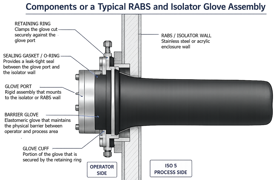
A barrier glove system includes more than the elastomeric glove. The integrity boundary may include:
- Glove or gauntlet
- Sleeve and cuff
- Retaining rings
- Gaskets or O-rings
- Glove port
- Mounting hardware
- Connections to the enclosure wall
Failure of any component can compromise separation between the operator or background environment and the aseptic processing zone.
This article establishes a validation-focused lifecycle for barrier glove systems, including:
- Intended use and risk classification
- Material and assembly selection
- Integrity-test method selection
- Test-equipment qualification
- Method-performance qualification
- Acceptance criteria
- Routine testing frequency
- Failure investigation and product-impact assessment
- Replacement and return to service
- Trending, change control, and requalification
Cleaning, disinfection, bio-decontamination, and physical integrity are related but separate controls. A passing integrity test does not establish microbiological cleanliness, and successful bio-decontamination does not prove that the glove assembly is free of leaks.
Barrier Glove System Boundary
The glove assembly must be treated as one installed barrier system. Testing only the elastomeric glove while excluding the cuff, retaining ring, gasket, port, or mounting interface may leave critical leak paths unchallenged.
The qualification boundary should identify:
- Glove material and thickness
- Glove size and length
- Sleeve or gauntlet configuration
- Cuff and retaining mechanism
- Gasket and seal arrangement
- Glove-port geometry
- Enclosure-wall interface
- Integrity-test connection
- Installed orientation
- Associated test equipment and software
The defined boundary should be included in the User Requirements Specification, drawings, component specifications, maintenance procedures, and qualification documentation.
Barrier Function and Loss-of-Integrity Risk
The consequence of a glove defect depends on the barrier design, pressure direction, glove location, process activity, and proximity to exposed sterile materials.
Potential failure modes include:
- Pinholes
- Cuts and punctures
- Tears
- Abrasion
- Cracking
- Seam failure
- Cuff damage
- Loose retaining rings
- Damaged or displaced gaskets
- Incorrect installation
- Chemical degradation
- Loss of elasticity
- Mechanical fatigue
- Permeation or compatibility failure in containment applications
A visible tear is only one type of failure. Small defects may not be detectable by visual inspection, while chemical or mechanical degradation may progressively reduce glove strength before an obvious breach occurs.
For a positive-pressure isolator, nominal leakage direction is outward. This reduces—but does not eliminate—the possibility of contamination ingress. Glove manipulation, pressure fluctuations, local airflow disturbances, and contact with contaminated inner surfaces may still create risk.
For a negative-pressure isolator, leakage direction is inward. Product-protection implications therefore require particular attention when negative pressure is used to provide containment.
RABS glove systems operate within and remain more dependent on the surrounding cleanroom. A defect may create a more direct interface between the Grade A processing zone and the background environment.
Product-impact assessments must therefore consider the actual system configuration rather than assuming that every glove failure has the same consequence.
Material Selection and Service-Life Definition
Barrier glove materials may include:
- Chlorosulfonated polyethylene
- EPDM
- Butyl rubber
- Neoprene
- Nitrile
- Other application-specific elastomers
Selection should be based on documented intended use rather than general material reputation.
The evaluation should address:
- Mechanical flexibility
- Puncture and tear resistance
- Fatigue resistance
- Chemical compatibility
- Compatibility with cleaning agents and disinfectants
- Compatibility with sporicidal agents
- Resistance to repeated VHP exposure
- Temperature and humidity exposure
- Product and process-chemical contact
- Particle shedding
- Permeation where containment is required
- Sterilization compatibility where applicable
- Operator reach and ergonomics
- Supplier controls and material consistency
Material-compatibility studies should represent cumulative lifecycle exposure, not only a single contact with a cleaning or bio-decontamination agent. Repeated chemical exposure, flexing, stretching, and aging may have combined effects that are not apparent from short-term compatibility data.
A maximum approved service life should be established from supplier information, qualification studies, exposure history, integrity-test data, and actual failure trends. Scheduled replacement provides an upper limit; it does not permit continued use of a glove showing damage or adverse performance before that limit is reached.
Glove Integrity Control Strategy
An effective program combines prevention, detection, response, and lifecycle review.
| Control element | Primary objective | Required evidence |
|---|---|---|
| Material and assembly selection | Prevent premature degradation | Approved specifications and compatibility assessment |
| Controlled installation | Prevent cuff, seal, and mounting defects | Installation procedure and post-installation test |
| Cleaning and disinfection | Control surface contamination | Approved procedure and compatibility evidence |
| Bio-decontamination or sterilization | Establish the required microbiological condition | Validated process appropriate to the barrier type |
| Visual inspection | Detect visible damage and installation problems | Documented inspection associated with use |
| Physical integrity testing | Detect leakage within the method capability | Qualified equipment, method, and acceptance criteria |
| Preventive replacement | Remove gloves before unacceptable degradation | Defined maximum life and replacement rationale |
| Failure response | Protect product and restore the barrier | Investigation, impact assessment, replacement, and retest |
| Trending and periodic review | Detect systematic deterioration | Glove-specific history and performance trends |
No single control provides complete assurance. Visual inspection cannot reliably detect small defects, and a physical test cannot establish surface microbiological condition.
Visual Inspection
Visual inspection should be performed under defined lighting and access conditions and should cover the complete visible glove assembly.
Inspection points should include:
- Fingertips
- Finger webs
- Palm
- Back of the hand
- Wrist
- Sleeve or gauntlet
- Cuff
- Retaining ring
- Gasket interface
- Glove-port connection
- Seams, where present
- Discoloration, tackiness, swelling, hardening, or cracking
The procedure should define how the glove is manipulated to expose folds and normally hidden surfaces without creating additional damage or disrupting first-air protection.
Visual inspection should be associated with each use and repeated after unusual manipulation, suspected contact with sharp equipment, maintenance, or another event that could affect integrity.
Visual inspection is not a substitute for a qualified physical integrity test.
Physical Integrity-Test Methods
Pressure-Decay Testing
Pressure-decay testing is commonly used for installed barrier gloves. The glove is inflated to a controlled pressure, allowed to stabilize, and monitored over a defined measurement period.
The result can be influenced by:
- Initial pressure
- Stabilization time
- Measurement duration
- Glove volume
- Material elasticity
- Glove temperature
- Ambient temperature
- Atmospheric pressure
- Glove position
- Test-port sealing
- Instrument resolution
- Movement or vibration
- Algorithm configuration
Pressure loss must not automatically be interpreted as leakage without considering elastic relaxation, temperature effects, equipment performance, and the validated test model.
Flow- or Leak-Rate Testing
Some automated systems measure the airflow required to maintain pressure or calculate a leak rate from pressure and flow data.
These methods can provide objective results but still require qualification for the specific glove assembly. A displayed numerical leak rate should not be accepted solely because it falls within a vendor default.
Gross-Leak Testing
Manual inflation or simplified pressure-hold tests may detect large tears, incorrect installation, or gross seal failures. They may be useful during maintenance or preliminary checks but may not provide the sensitivity, repeatability, or electronic documentation required for routine GMP release decisions.
Tracer-Gas and Specialized Methods
Tracer-gas or other high-sensitivity methods may be used during development, investigation, or specialized containment qualification. Their suitability for routine testing depends on practicality, test boundary, required sensitivity, recovery, and the possibility of introducing contaminants into the barrier system.
Integrity-Test Method Selection
The selected method should be appropriate for:
- RABS or isolator design
- Positive- or negative-pressure operation
- Glove material and size
- Glove and sleeve volume
- Port geometry
- Installed test orientation
- Required defect-detection capability
- Test duration
- Production schedule
- Data-record requirements
- Product and operator risk
- Applicable regulatory expectations
There is no universal pressure, test time, or allowable pressure-decay value suitable for every barrier glove. Acceptance criteria must be established for the installed configuration and supported by method-performance evidence.
The test pressure must be high enough to support reliable detection but must not stretch, damage, or permanently deform the glove assembly.
Integrity-Test Equipment Qualification
Dedicated glove-integrity testers are GMP instruments when their results support equipment release, batch assessment, or confirmation of barrier integrity.
User Requirements
The URS should define:
- Intended glove systems
- Required measurement range
- Required sensitivity
- Accuracy and resolution
- Test-pressure range
- Stabilization and measurement controls
- Approved recipes
- Automatic pass/fail evaluation
- Invalid-test handling
- Glove and location identification
- Calibration requirements
- Data recording and retention
- User access
- Audit-trail requirements where applicable
- Report content
- Backup and recovery
- Portable-use requirements
- Environmental operating limits
Design Qualification
Design Qualification should evaluate whether the proposed tester and test method can support the intended glove materials, volumes, port designs, operating locations, and required defect-detection capability.
DQ should also evaluate:
- Test-adapter design
- Potential for adapter leakage
- Pressure-control strategy
- Sensor range and accuracy
- Temperature compensation
- Test algorithm
- Electronic record controls
- Calibration standards
- Known-leak or reference-leak capability
- Cleaning and transfer requirements for portable equipment
Installation Qualification
Installation Qualification should verify:
- Manufacturer, model, and serial number
- Hardware and software versions
- Pressure sensors and flow devices
- Test hoses and adapters
- Electrical supply
- Communication interfaces
- Instrument identification
- Calibration status
- Approved manuals
- Installed recipes and configuration
- User accounts and security settings
- Data-storage and backup configuration
For portable testers, IQ should define the approved configuration and accessories rather than tying qualification to one permanent physical location.
Operational Qualification
Operational Qualification should challenge the tester throughout its intended operating range.
Testing should include:
- Pressure generation and control
- Sensor accuracy
- Timing accuracy
- Stabilization logic
- Measurement calculations
- Alarm and interlock functions
- Pass/fail logic
- Blank or sealed-reference testing
- Certified or characterized reference-leak challenges
- Repeatability
- Temperature sensitivity
- Loss of power
- Aborted tests
- Invalid-test recognition
- User access
- Recipe control
- Report accuracy
- Electronic record retention
- Audit trails where applicable
- Backup and recovery
A reference leak demonstrates the detection capability of the test system under defined conditions. It does not replace calibration of pressure, flow, temperature, or timing instruments.
Method Performance Qualification
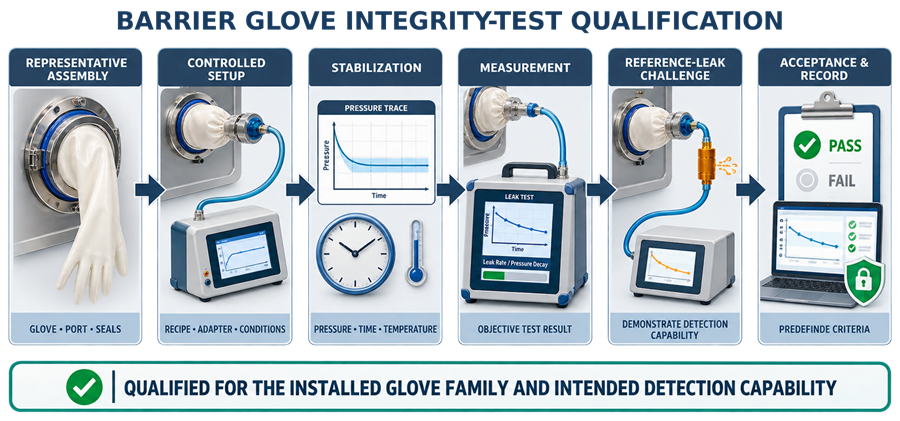
Performance Qualification should demonstrate reliable operation with representative installed glove assemblies.
The study should address:
- Each justified glove-material family
- Glove size and internal volume
- Sleeve length
- Port design
- Installed orientation
- New and appropriately aged conditions
- Representative temperature range
- Maximum expected test-system volume
- Operator setup
- Adapter installation
- Repeated measurements
- Reference-leak or characterized defect challenges
- False-pass and false-fail risk
- Test duration
- Method robustness
Artificial defects should be created only in sacrificial test assemblies. Their dimensions and limitations should be documented. A calibrated or characterized reference leak may provide more reproducible method challenges than manually produced pinholes.
Method capability should be demonstrated at or beyond the proposed acceptance boundary. Qualification should not rely only on successful tests of intact gloves.
Acceptance Criteria and Test Validity
Acceptance criteria should be approved before execution and should include, as applicable:
- Permitted starting-pressure range
- Stabilization requirements
- Measurement duration
- Maximum pressure decay
- Maximum calculated leak rate
- Environmental operating range
- Permitted temperature change
- Adapter leak requirements
- Instrument-status requirements
- Criteria for an invalid test
- Pass/fail decision logic
- Required electronic record
- Review and approval requirements
The criteria should account for method precision, instrument accuracy, measurement uncertainty, glove elasticity, and environmental influence.
A passing test means that no leakage exceeding the qualified method’s acceptance boundary was detected under the test conditions. It does not establish the absence of every microscopic defect or prove that the glove surface is microbiologically acceptable.
Repeated testing must not be used to test a failed glove into compliance. Retesting is appropriate only when a predefined, scientifically supportable reason demonstrates that the original test was invalid—for example, a confirmed adapter leak, interrupted test, incorrect recipe, or instrument malfunction.
Installation and Replacement Control
Installation should be performed under an approved procedure that defines:
- Correct glove material, size, and part number
- Incoming inspection
- Supplier lot and traceability
- Sterilization status where applicable
- Port and gasket inspection
- Cuff positioning
- Retaining-ring installation
- Prevention of twisting or excessive stretching
- Post-installation visual inspection
- Post-installation physical integrity testing
- Required cleaning, sterilization, or bio-decontamination
- Documentation and system release
A replacement glove should not be returned to operation solely because it appears correctly installed. The complete installed assembly must pass the applicable integrity test and meet the required microbiological preparation state.
Cleaning, Disinfection, and Bio-Decontamination Interface
Cleaning removes residues and soils. Disinfection or bio-decontamination establishes the required surface microbiological condition. Physical integrity testing evaluates leakage. Each activity has a different purpose.
The control strategy should address:
- Process-side glove surface
- Operator-side or inner glove surface
- Cuff and port areas
- Chemical compatibility
- Agent concentration and contact time
- Wiping and manipulation technique
- Glove position during treatment
- Drying or aeration
- Residue control
- Maximum cumulative exposure
For isolator bio-decontamination, gloves should be positioned so that the agent can reach folds, fingers, cuffs, and normally shadowed surfaces. Detailed requirements belong in Barrier System Bio-Decontamination Validation.
For RABS used in Grade A processing, glove preparation must be integrated with the system’s sterilization or validated bio-decontamination strategy.
A passing leak test does not release a newly installed glove for use until the required cleaning, sterilization, disinfection, or bio-decontamination steps have also been completed.
Routine Testing and Inspection Frequency
Testing frequency should be documented and justified according to:
- Barrier type
- System pressure
- Batch or campaign duration
- Number and complexity of interventions
- Glove material
- Expected mechanical loading
- Cleaning and bio-decontamination exposure
- Historical failure rate
- Manufacturer recommendations
- Product risk
- Applicable market requirements
- Contamination control strategy
The FDA aseptic processing guidance recommends visual evaluation with every use, routine physical-integrity testing, preventive maintenance, and justified replacement frequencies for isolator gloves.
For operations subject to EU GMP Annex 1:
- Isolator glove integrity testing is generally expected at the beginning and end of each batch or campaign.
- Additional testing may be required for extended campaigns.
- Visual inspection should be associated with each use and following manipulation that could affect integrity.
- RABS gloves should be visually examined with each use and integrity-tested at defined periodic intervals.
The isolator and RABS requirements should not be collapsed into one universal frequency.
Additional testing triggers may include:
- New glove installation
- Glove replacement
- Suspected contact with a sharp surface
- Unusual resistance during manipulation
- Maintenance affecting the glove or port
- Disassembly or adjustment of retaining components
- Unexpected pressure behavior
- Extended shutdown
- Relocation or modification of the glove port
- Adverse trend or repeated invalid tests
The test sequence relative to cleaning, bio-decontamination, production, and batch release should be defined and validated.
Response to a Failed Integrity Test
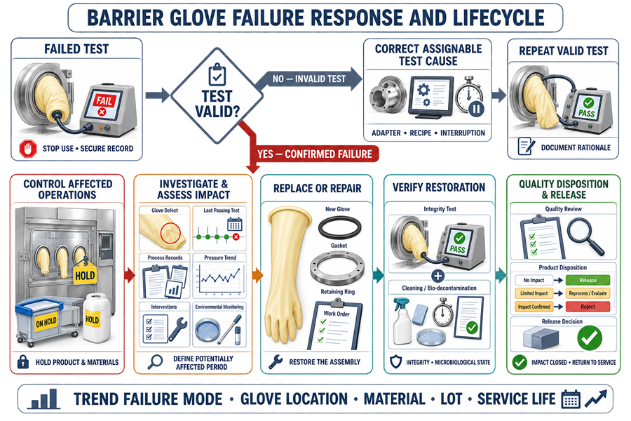
A failed integrity test is a potential barrier breach requiring immediate control. Initial actions should include:
- Stop affected operations
- Prevent further use of the glove
- Identify the glove and location
- Secure the original test record
- Verify instrument and adapter status
- Determine whether the test was valid
- Place potentially affected product or materials under appropriate control
- Notify Production and Quality
If the test is valid, the failure should not be cleared through repeated testing. The glove assembly should be inspected and the defect localized where practical.
The investigation should evaluate:
- Last passing integrity test
- Time interval potentially affected
- Batches or campaigns processed
- Glove location
- Defect type and size
- Proximity to exposed critical sites
- Interventions performed
- Pressure direction
- Pressure and alarm history
- Airflow implications
- Environmental monitoring
- Cleaning and bio-decontamination history
- Operator observations
- Maintenance history
- Glove age and exposure history
- Similar failures in other locations
A glove failure discovered after production does not establish the exact time at which integrity was lost. The potentially affected period must be determined through documented scientific assessment.
Corrective actions may include:
- Glove replacement
- Gasket or retaining-component replacement
- Port repair
- Successful post-repair integrity testing
- Cleaning and bio-decontamination
- Targeted system testing
- Procedure revision
- Operator retraining
- Supplier investigation
- CAPA
- Requalification
- Review of Media Fill and Aseptic Process Simulation coverage
The Quality Unit should determine product disposition using the complete evidence set. A passing test after replacement does not resolve the impact of the preceding failure.
Return to Service
Return to service should require documented confirmation that:
- The failed component was replaced or repaired
- The cause was addressed
- The complete installed assembly passed integrity testing
- Required cleaning or bio-decontamination was completed
- Associated alarms and instruments are functional
- Product-impact assessment was completed
- Required qualification testing was completed
- Deviations and work orders were closed or formally controlled
- Quality approval was obtained
Where glove replacement or repair could affect airflow, intervention reach, enclosure integrity, or bio-decontamination distribution, the return-to-service assessment should consider targeted airflow studies, system leak testing, bio-decontamination verification, or broader requalification.
Trending and Continued Verification
Each glove should have a traceable lifecycle history.
Records should permit trending by:
- Barrier system
- Glove-port location
- Glove material
- Manufacturer and part number
- Supplier lot
- Installation date
- Test date
- Numerical test result
- Pass, fail, or invalid status
- Invalid-test reason
- Cleaning or decontamination cycles
- Manufacturing campaigns
- Replacement date
- Replacement reason
- Defect location
- Failure mechanism
- Operator or tester
- Test-equipment identification
Trending should distinguish confirmed glove failures from invalid tests caused by adapters, setup, environmental instability, or test-equipment problems.
Adverse trends may include:
- Increasing pressure decay
- Increasing calculated leak rate
- Repeated failures at one port
- Shortening service life
- Higher failure rate for one material or supplier lot
- Increased invalid-test frequency
- Failures associated with particular interventions
- Failures following specific cleaning or VHP exposures
- Recurring gasket or retaining-ring problems
Trend evaluation should support preventive replacement, supplier management, maintenance changes, method improvement, and requalification decisions.
Change Control and Requalification
Changes should be evaluated through GMP Change Control and Validation Impact Assessment.
Potentially significant changes include:
- Glove material
- Thickness, size, or sleeve length
- Manufacturer or manufacturing site
- Port or cuff design
- Gasket material
- Retaining mechanism
- Cleaning or disinfecting agent
- Bio-decontamination cycle
- Integrity-test pressure
- Stabilization or measurement time
- Acceptance criteria
- Test adapter
- Tester hardware
- Sensor replacement
- Software or algorithm
- Electronic record configuration
- Testing frequency
- Maximum approved service life
The requalification scope should be selected according to impact. It may include:
- Material-compatibility assessment
- Installation verification
- Reference-leak challenges
- Repeatability testing
- Revised acceptance-criteria studies
- In-situ method performance testing
- Data-integrity verification
- Bio-decontamination studies
- Airflow visualization
- APS assessment
The approach should follow Risk-Based Requalification of GMP Equipment rather than automatically repeating every original qualification test.
Periodic Review
Periodic review should evaluate whether the glove program remains effective and supported by current evidence.
Review inputs should include:
- Integrity-test results and trends
- Invalid tests
- Visual-inspection findings
- Failure investigations
- Product-impact assessments
- Glove service life
- Replacement history
- Maintenance records
- Calibration status
- Reference-leak checks
- Supplier changes
- Cleaning and bio-decontamination exposure
- Software and configuration changes
- Deviations and CAPA
- Applicable regulatory changes
- Requalification status
The review should conclude whether:
- The current material remains suitable
- Test acceptance criteria remain justified
- Test frequency remains appropriate
- Service-life limits remain suitable
- Additional preventive controls are required
- Requalification is necessary
- Regulatory Framework
In the United States, barrier glove controls support compliance with:
- 21 CFR 211.42, covering facility design and aseptic processing controls
- 21 CFR 211.63, requiring equipment suitable for its intended use
- 21 CFR 211.67, covering equipment cleaning and maintenance
- 21 CFR 211.113(b), requiring procedures and validation to prevent microbiological contamination
- FDA Guidance for Industry: Sterile Drug Products Produced by Aseptic Processing
- FDA Compliance Program 7356.002A, which identifies glove integrity as a key isolator-control element
For EU-regulated operations, EU GMP Annex 1 provides specific expectations for glove materials, visual examination, integrity-testing frequency, replacement strategy, and bio-decontamination.
ISO 14644-7:2004 addresses separative devices, including isolators and gloveboxes. It does not provide a complete pharmaceutical glove-integrity validation strategy or universal acceptance criteria.
Common Deficiencies
Common deficiencies include:
- Testing only the elastomeric glove while excluding seals and mounting interfaces
- Treating visual inspection as a complete integrity test
- Using an unqualified glove tester
- Accepting vendor default criteria without site-specific justification
- Qualification using only intact gloves
- No reference-leak or defect-detection challenge
- Failure to account for stabilization, elasticity, or temperature
- Test pressure that can damage the glove
- Repeated retesting after an initial failure
- No predefined invalid-test criteria
- Applying the same frequency to RABS and isolators without justification
- No post-installation test after replacement
- Confusing physical integrity with microbiological condition
- No retrospective product-impact assessment
- Service life based only on elapsed time
- Failure data not linked to glove location, lot, or exposure history
- Uncontrolled changes to recipes, adapters, software, or acceptance criteria
- Requalification based solely on calendar frequency
Conclusion
Barrier glove integrity is maintained through an integrated lifecycle, not through one periodic leak test. The program must control material selection, assembly design, installation, microbiological preparation, visual inspection, physical integrity testing, failure response, replacement, trending, and change management.
The integrity-test method and equipment must be qualified for the installed glove assemblies and intended detection capability. Acceptance criteria must be scientifically justified, and failures must trigger documented investigation and product-impact assessment.
Continued assurance depends on objective evidence that each glove assembly remains suitable throughout its approved service life and that changes, failures, and adverse trends receive an appropriate validation response.