

Moist Heat Sterilization Principles and Cycle Types
Moist heat sterilization uses controlled thermal exposure in the presence of moisture to inactivate microorganisms. Saturated steam is the most common heating medium, but moist-heat processes also include steam–air mixtures, heated-water spray or cascade systems, water immersion, and other configurations used to heat sealed liquid containers.
Successful moist heat sterilization depends on more than reaching a nominal chamber temperature. The process must deliver sufficient thermal lethality to the defined sterilization target while controlling air removal, steam contact, condensate, load configuration, container pressure, heating, cooling, and product exposure.
The correct cycle depends on how heat reaches the target:
- Direct condensation of steam on exposed load surfaces
- Steam penetration into porous or wrapped loads
- Indirect heat transfer through a sealed container into a liquid
- Direct steam contact with the internal surfaces of an installed process system
These applications use related moist-heat principles but require different cycle designs, measurements, qualification studies, and routine controls.
Purpose and Scope
This article addresses:
- Saturated-steam heat transfer
- Moist-heat microbial lethality
- Temperature, time, and F₀
- The saturated-steam pressure–temperature relationship
- Air removal and steam penetration
- Condensate generation and drainage
- Physical steam-quality attributes
- Gravity-displacement cycles
- Dynamic-air-removal cycles
- Steam-flush pressure-pulse cycles
- Porous and wrapped loads
- Liquid-load cycles
- Air-overpressure and heated-water processes
- Typical cycle phases and critical parameters
- Product, package, and load considerations
- The boundary between autoclave processing and steam-in-place
- The relationship between process principles, development, qualification, and routine control
The broader selection boundary between moist heat and other sterilization methods is addressed separately.
Moist Heat as a Sterilization Process
Moist heat inactivates microorganisms principally through thermal damage to cellular components, including proteins, membranes, and essential metabolic systems. Moisture normally increases the effectiveness of heat relative to a dry environment at the same temperature.
The process outcome depends on the combined effect of:
- Temperature at the sterilization target
- Duration of exposure
- Microbial population
- Microbial heat resistance
- Moisture availability
- Heat-transfer mechanism
- Air removal or venting
- Load configuration
- Product and package characteristics
- Process reproducibility
The chamber temperature is not necessarily the temperature at the most difficult-to-heat location. For direct-contact loads, the critical location may be inside a porous pack, a narrow lumen, a wrapped assembly, or an area where air remains trapped. For sealed liquids, the critical location is within the product and may move during heating or cooling because of convection.
Saturated Steam and Latent-Heat Transfer
Saturated steam exists in equilibrium with liquid water at a corresponding temperature and pressure. When saturated steam contacts a cooler surface, it condenses and releases latent heat.
This phase change provides rapid heat transfer to:
- Equipment surfaces
- Hard goods
- Wrapped components
- Porous materials
- Container exteriors
- Installed process-system surfaces
For direct-contact steam sterilization, the effective heat-transfer sequence is:
Saturated steam → surface contact → condensation → latent-heat release → load heating
Continuous steam contact requires the generated condensate to move away from the surface so that additional steam can condense. Air, non-condensable gases, inadequate venting, poor load arrangement, or accumulated condensate can interfere with this process.
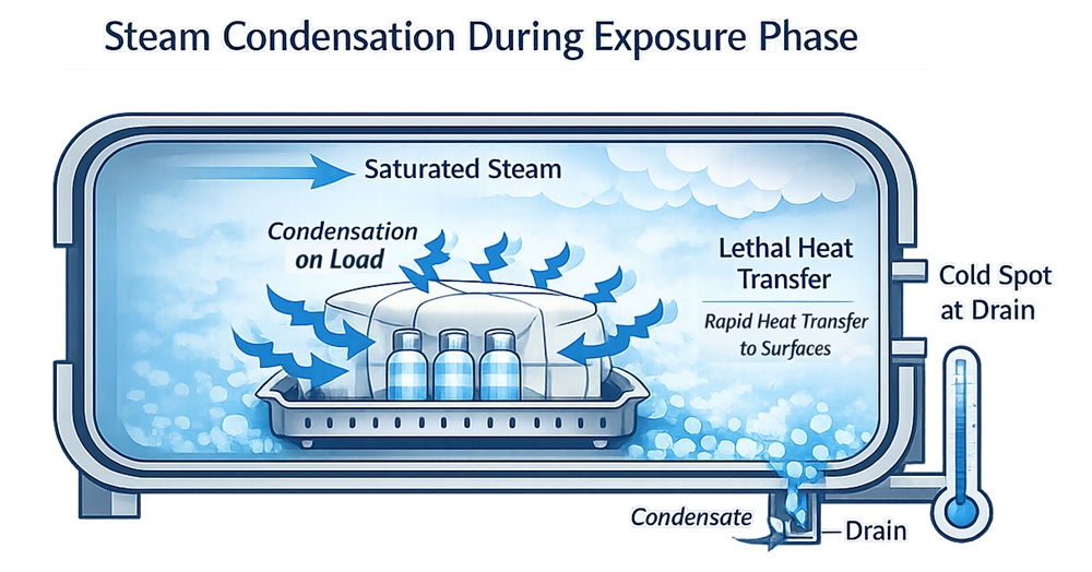
The illustration shows the correct central principle: steam condenses on cooler load surfaces, releases heat, and produces condensate that must be removed. The chamber drain is an important monitoring location, but it should not automatically be declared the coldest location for every sterilizer and every cycle.
Saturated-Steam Pressure–Temperature Relationship
Saturated steam has a defined thermodynamic relationship between temperature and absolute pressure. At equilibrium, each saturation temperature corresponds to a particular saturation pressure.
This relationship can support assessment of chamber conditions, but several limitations must be understood:
- Pressure must be interpreted as absolute pressure, not gauge pressure, when compared with steam tables.
- Atmospheric pressure affects the conversion between gauge and absolute pressure.
- A matching chamber temperature and pressure does not prove that steam contacted every load location.
- Entrapped air can produce misleading local conditions.
- Instrument error can create an apparent temperature–pressure discrepancy.
- A steam–air mixture does not follow the pure saturated-steam relationship.
- Superheated steam can exist at a temperature above the saturation temperature corresponding to the measured pressure.
Temperature–pressure comparison is therefore an important diagnostic and control tool, but it does not replace air-removal testing, steam-quality assessment, heat-distribution studies, or load-penetration studies.
Superheated Steam
Superheated steam has been heated above the saturation temperature corresponding to its pressure. It does not immediately condense when it contacts a surface that is above the applicable saturation temperature.
Because condensation is delayed, superheated steam does not transfer heat in the same manner as saturated steam. Excessive superheat can therefore interfere with direct-contact steam sterilization.
Potential causes include:
- Excessive pressure reduction
- Inadequate steam conditioning
- Improperly designed steam distribution
- Excessively dry steam
- Heat input after steam generation
- High-temperature load materials that initially heat the entering steam
- Equipment or cycle conditions that prevent prompt condensation
Localized temperature behavior inside a porous load should not automatically be classified as utility-level superheat. Load absorption, retained heat, moisture exchange, and sensor placement can produce local effects that require separate scientific assessment.
Air Removal and Steam Penetration
Entrapped air is a major failure mechanism in direct-contact moist heat sterilization. Air can prevent steam from contacting the sterilization target, reduce heat-transfer efficiency, delay heating, and create low-lethality locations.
Potential air-retention locations include:
- Wrapped components
- Textile or porous packs
- Tubing and lumens
- Nested containers
- Inverted vessels
- Closed or partially closed valves
- Filter housings
- Equipment cavities
- Poorly vented chamber locations
- High points in installed piping
- Dead legs and instrument branches
Air may be removed by:
- Gravity displacement
- Mechanical vacuum
- Alternating vacuum and steam pulses
- Steam-flush pressure pulses
- Controlled venting from installed systems
- Displacement through designated low-point or high-point exits
The selected method must be demonstrated with the actual load or system configuration. An empty-chamber air-removal test does not independently establish steam penetration into every production load.
Condensate and Drainage
Condensate is an expected result of saturated-steam heat transfer. Its formation is necessary, but its accumulation can create process problems.
Uncontrolled condensate may cause:
- Wet loads
- Delayed heating
- Uneven temperature distribution
- Insulation of load surfaces
- Blocked air-removal paths
- Water hammer
- Container damage
- Filter wetting
- Corrosion
- Post-cycle handling problems
Drainage depends on:
- Chamber and piping slope
- Load orientation
- Rack and cart design
- Steam-trap capacity
- Drain-screen condition
- Jacket operation
- Steam flow
- Cycle pressure
- Quantity and thermal mass of the load
- Condensate-return configuration
The chamber drain is frequently monitored because it is a likely location for air and condensate removal and may represent a difficult heating location. Its actual relationship to the coldest chamber or load position must be established through study rather than assumed.
Moist-Heat Lethality
Moist-heat lethality integrates the effect of temperature over time relative to a defined reference temperature and z-value.
For conventional F₀ calculations:
F₀ = ∫ 10^((T(t) − 121.1)/z) dt
where:
- F₀ is the equivalent exposure time at 121.1°C
- T(t) is the measured temperature at time t
- z is the temperature change required to change the D-value by a factor of ten
- A z-value of 10°C is conventionally used for F₀ unless another value is scientifically justified
F₀ is calculated from the complete temperature history at the measurement location. Heat delivered below 121.1°C contributes less lethality per unit time, while heat delivered above 121.1°C contributes more.
F₀ should not be treated as a universal acceptance criterion. The required lethality depends on:
- Initial bioburden
- Microbial resistance
- Required sterility assurance level
- Product and package limitations
- Cycle-development strategy
- Minimum acceptable process margin
- Maximum acceptable product exposure
- Applicable regulatory commitments
A high calculated F₀ at one sensor does not prove adequate lethality throughout the entire load.
Temperature Distribution and Heat Penetration
Temperature distribution and heat penetration answer different questions.
| Study | Principal question |
|---|---|
| Empty-chamber heat distribution | Can the sterilizer establish uniform and controlled thermal conditions without a production load? |
| Loaded-chamber heat distribution | How does the defined load affect chamber conditions? |
| Heat penetration | Does the required temperature and lethality reach the most difficult-to-heat locations within the product, pack, assembly, container, or system? |
| Microbiological challenge | Does the process provide the intended microbial inactivation at defined challenge locations? |
The physical studies must be designed around the expected heat-transfer path. A chamber sensor cannot substitute for a penetration sensor inside a liquid container, porous pack, tubing assembly, filter housing, or installed process branch.
Detailed study design is addressed in Temperature Mapping and Heat Distribution.
Typical Moist-Heat Cycle Phases
A moist-heat cycle may contain the following phases:
Conditioning
The system establishes the required initial state through air removal, steam admission, pressure pulsing, venting, preheating, or another defined sequence.
Heating
The chamber and load increase toward the required exposure conditions. The load may lag behind the chamber because of thermal mass, insulation, container geometry, or restricted steam access.
Equilibration
The coldest defined measurement locations reach the required exposure range. The exposure timer should not begin solely because the chamber control sensor reached its setpoint unless that logic has been scientifically justified.
Exposure
The defined process parameters are maintained for the required time. Parameters may include temperature, pressure, exposure duration, steam condition, chamber atmosphere, circulation, or overpressure.
Exhaust and Cooling
Steam or heated water is removed and the load is cooled under controlled conditions. For sealed liquids, exhaust and cooling must prevent boil-over, closure movement, bag deformation, container breakage, or loss of integrity.
Drying
Direct-contact wrapped or porous loads may use vacuum and jacket heat to remove residual moisture. Drying is not normally the same objective for sealed liquid loads.
Cycle Completion and Release
The control system confirms that required phases and parameters were completed without disqualifying alarms or interruptions. Cycle completion by the PLC does not by itself constitute GMP load release.
Moist-Heat Cycle Types and Heat-Transfer Paths
Cycle names vary among equipment manufacturers. The process should therefore be defined by its actual operating phases, air-removal method, heating medium, pressure strategy, load type, and heat-transfer path.
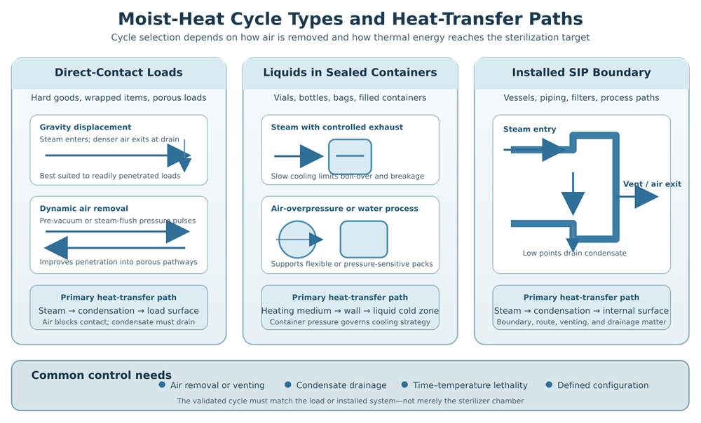
The illustration separates three applications that should not be evaluated as though they were identical autoclave cycles:
- Direct steam contact with hard goods, wrapped items, or porous loads
- Indirect heating of a liquid through its sealed container
- Direct steam contact with an installed SIP boundary
Cycle-Type Comparison
| Cycle type | Typical application | Air-removal or pressure strategy | Principal heat-transfer path | Important risks |
| Gravity displacement | Readily penetrated hard goods, open containers, selected wrapped loads | Steam displaces denser air toward an open drain or vent | Steam condenses directly on exposed surfaces | Air retention, slow penetration, load orientation, condensate |
| Pre-vacuum or vacuum-pulse | Porous loads, wrapped components, tubing, complex assemblies | Mechanical vacuum followed by steam admission; multiple pulses may be used | Steam penetrates the load and condenses on internal and external surfaces | Vacuum leaks, inadequate pulse depth, blocked pathways, wet loads |
| Steam-flush pressure-pulse | Selected porous and hard-goods loads | Repeated steam admission and pressure reduction without deep vacuum | Steam progressively displaces air and penetrates the load | Inadequate pulse sequence, load resistance, retained air |
| Liquid cycle with controlled exhaust | Aqueous product in rigid sealed containers | Limited air-removal demand; controlled depressurization and cooling | Chamber steam heats container wall, which heats the liquid | Slow penetration, boil-over, closure movement, breakage |
| Steam–air mixture with overpressure | Flexible containers, bags, plastic bottles, pressure-sensitive packs | Controlled mixture and circulation maintain external support pressure | Steam–air atmosphere heats the container and liquid | Atmosphere uniformity, circulation, pressure differential, cooling |
| Heated-water spray or cascade | Sealed liquid containers and flexible packages | Pumped water distribution with controlled air overpressure where required | Heated water transfers heat through the container wall | Spray coverage, circulation, nozzle blockage, water temperature, overpressure |
| Water immersion | Selected sealed containers or medical-device applications | Load submerged in circulating heated water; overpressure may be applied | Water transfers heat through the container or package | Water circulation, temperature uniformity, container pressure, cooling |
| Steam-in-place | Installed vessels, piping, filters, and process pathways | Controlled steam routing, venting, air displacement, and condensate drainage | Steam condenses directly on internal product-contact surfaces | Boundary definition, trapped air, poor drainage, valve state, cold branches |
Gravity-Displacement Cycles
In a gravity-displacement cycle, steam entering the chamber displaces cooler, denser air toward the drain or vent.
The process is generally most suitable for loads that permit ready air displacement and steam access. Its suitability decreases as load porosity, wrapping, internal pathways, or geometric complexity increase.
Development should evaluate:
- Steam-entry and air-exit locations
- Load orientation
- Openings and internal cavities
- Nested components
- Wrapping
- Load density
- Condensate drainage
- Heating lag
- Cold-location reproducibility
Gravity displacement should not be selected solely because a load eventually reaches the required chamber temperature. The study must demonstrate that air is removed and steam reaches the required locations reproducibly.
Dynamic-Air-Removal Cycles
Dynamic-air-removal cycles use mechanical vacuum, steam pulses, pressure pulses, or combinations of these actions before exposure.
Pre-Vacuum Cycles
A pre-vacuum cycle removes chamber and load air before the principal steam-exposure phase. Multiple vacuum and steam pulses may be used.
These cycles are commonly applied to:
- Porous loads
- Wrapped components
- Stopper loads
- Garments
- Filters
- Tubing assemblies
- Equipment parts with internal pathways
Performance depends on:
- Chamber leak tightness
- Vacuum depth
- Pulse number
- Pulse rate
- Steam admission
- Load resistance
- Pathway configuration
- Drain and vent performance
Vacuum capability must be evaluated with the intended load. A successful empty-chamber leak test does not prove air removal from a complex production configuration.
Steam-Flush Pressure-Pulse Cycles
Steam-flush pressure-pulse cycles remove air through repeated steam admission and pressure reduction without necessarily pulling a deep vacuum.
These cycles may be useful where:
- The load can be penetrated by pressure pulsing
- Deep vacuum could damage components or packages
- The sterilizer is specifically designed for this method
- The pulse sequence has been developed for the load
The cycle should define pulse pressures, number of pulses, steam-flow conditions, venting, transition criteria, and the conditions required before exposure begins.
Porous and Wrapped Loads
Porous and wrapped loads create resistance to air removal and steam penetration.
Examples include:
- Garments
- Textile packs
- Filters
- Stopper bags
- Wrapped equipment parts
- Tubing assemblies
- Porous components
- Dense packaged assemblies
Important load variables include:
- Material type
- Moisture absorption
- Pack density
- Wrap material
- Fold pattern
- Container or bag closure
- Component orientation
- Internal pathway length
- Load position
- Minimum and maximum load size
- Proximity to chamber walls and drain
- Drying requirement
A load may reach acceptable external temperatures while still retaining air or heating slowly internally. Penetration sensors and appropriately justified biological indicators should target the locations expected to be most difficult to sterilize.
Detailed worst-case selection is addressed in Load Development Strategy.
Liquid-Load Cycles
For a sealed liquid container, chamber steam does not directly contact the product. Heat must pass through the container wall before it reaches the liquid.
The heat-transfer sequence is:
Chamber heating medium → container exterior → container wall → liquid → cold zone
Liquid heating may occur through:
- Conduction
- Natural convection
- Forced movement caused by the process or container orientation
- A combination of conduction and convection
The cold location within a liquid container is not necessarily the geometric center. Its position depends on:
- Container shape
- Fill volume
- Product viscosity
- Container orientation
- Heating rate
- Convection pattern
- Headspace
- Product composition
Penetration studies must place temperature sensors in scientifically justified product locations and must address representative and worst-case container configurations.
Exhaust and Cooling
Liquid cycles require controlled exhaust and cooling because rapid chamber depressurization can cause the liquid to boil or create an excessive pressure difference across the container.
Potential consequences include:
- Boil-over
- Stopper movement
- Closure leakage
- Vial breakage
- Bottle deformation
- Bag rupture
- Seal damage
- Loss of container-closure integrity
The cycle may use:
- Slow exhaust
- Controlled chamber-pressure reduction
- Sterile-air overpressure
- Steam–air mixture
- Water spray or cascade
- Water immersion
- Controlled cooling water
- Combined air and water cooling
The selected process must protect container integrity while maintaining the required minimum lethality and controlling maximum product exposure.
USP <1229.2> provides technical information relevant to moist-heat sterilization of aqueous liquids.
Steam–Air Mixture and Air-Overpressure Processes
Steam–air mixture cycles intentionally contain both steam and air. They are not pure saturated-steam cycles.
Air may provide external pressure support for flexible containers, but it also changes heat-transfer behavior. The process may require active circulation to maintain a uniform chamber atmosphere.
Critical parameters may include:
- Chamber temperature
- Total pressure
- Steam contribution
- Air contribution
- Fan or circulation performance
- Heating rate
- Cooling rate
- Overpressure
- Product temperature
- Water temperature where applicable
Pure-steam saturation tables cannot be used as the sole basis for interpreting a steam–air mixture. Temperature, total pressure, mixture control, circulation, and product response must be evaluated together.
Heated-Water Processes
Water-spray, water-cascade, and water-immersion processes are moist-heat sterilization methods even though direct saturated-steam contact is not the primary heating mechanism.
Their effectiveness depends on:
- Water temperature
- Water distribution
- Pump and circulation performance
- Spray-nozzle coverage
- Load orientation
- Heat-exchanger performance
- Chamber pressure
- Container exposure
- Cooling control
- Water-system hygienic condition
These processes may be appropriate for sealed containers that require controlled pressure support or more uniform cooling.
They should not be qualified using assumptions developed for direct-contact saturated-steam cycles.
Steam Quality
Steam quality has both physical and chemical dimensions.
Physical Steam Quality
Physical steam quality for direct-contact sterilization commonly includes:
- Dryness
- Non-condensable gases
- Superheat
- Pressure stability
- Ability to condense at the point of use
Excess moisture can contribute to wet loads and poor process performance. Excessive non-condensable gases can interfere with contact and heat transfer. Excessive superheat can delay condensation.
Acceptance criteria should come from the applicable equipment design, standard, process requirement, and validation strategy. A single universal dryness-fraction limit should not be inserted into every pharmaceutical sterilization process without an applicability assessment.
Chemical and Microbiological Quality
Where steam or condensate contacts product-contact surfaces, components, or materials, the steam source may require controls over:
- Feed-water quality
- Volatile and nonvolatile contaminants
- Additives
- Endotoxin where applicable
- Condensate quality
- Distribution-system materials
- Sampling locations
- Point-of-use condition
Physical steam-quality testing and chemical condensate testing answer different questions. Passing one does not establish the other.
Utility generation, distribution, sampling, monitoring, and requalification are addressed in Clean Steam System Qualification, Monitoring, and Requalification.
Critical Process Parameters and Monitored Attributes
The applicable parameters depend on the cycle type.
| Parameter or attribute | Direct-contact loads | Sealed liquid loads | SIP |
| Chamber or system temperature | Critical | Critical | Critical |
| Exposure time | Critical | Critical | Critical |
| Pressure | Supports control and diagnosis | Critical to container protection | Supports control and diagnosis |
| Air-removal pulse conditions | Often critical | Cycle-dependent | Venting or displacement is critical |
| Product or load temperature | Critical during qualification | Critical during qualification and often development | Critical at worst-case branches |
| Condensate drainage | Critical | Important | Critical |
| Steam dryness, NCG, and superheat | Commonly applicable | Applicability depends on heating process | Applicable to direct steam contact |
| Air overpressure | Normally not used during exposure | May be critical | Application-dependent |
| Water temperature and circulation | Not applicable | Critical for water processes | Normally not applicable |
| Load or route configuration | Critical | Critical | Critical |
| Cooling rate | Drying and handling concern | Often critical to product and package | Relevant to boundary protection |
| Delivered lethality | Required | Required | Required |
Setpoints, operating ranges, alarm limits, acceptance criteria, and validated limits should not be treated as interchangeable.
Product and Package Compatibility
Adequate microbial lethality does not establish that the product remains acceptable.
Development should evaluate potential effects on:
- Potency
- Degradation products
- pH
- Appearance
- Viscosity
- Protein stability
- Particulates
- Extractables and leachables
- Container deformation
- Closure movement
- Seal strength
- Package integrity
- Filter performance
- Component functionality
- Material aging
The process must establish both:
- A minimum exposure sufficient for sterility assurance
- A maximum exposure that preserves product, component, and package quality
Minimum lethality and maximum product exposure may occur at different locations in the same load.
Steam-in-Place Boundary
Steam-in-place applies moist-heat sterilization principles to an installed process system rather than to removable items inside an autoclave chamber.
A typical SIP boundary may include:
- Vessels
- Product piping
- Transfer paths
- Filters and filter housings
- Valve matrices
- Sampling paths
- Instrument branches
- Nozzles
- Spargers
- Vent paths
- Condensate drains
The common scientific principles remain:
- Steam contact
- Air removal
- Condensation
- Heat transfer
- Drainage
- Time–temperature lethality
- Worst-case-location evaluation
The system architecture creates additional requirements for:
- Defined sterilized boundaries
- Approved valve states
- Steam-entry points
- High-point venting
- Low-point drainage
- Branch and dead-leg assessment
- Sterile-boundary closure
- Post-cycle protection
- Recipe control
- Interaction with CIP
- Route-specific qualification
This article establishes only the common moist-heat science and the boundary with SIP. Complete SIP architecture, cycle development, automation, functional testing, sterile-boundary control, and requalification are addressed in Steam-in-Place Utility Systems.
An autoclave load should not be described as SIP merely because steam is used. Likewise, qualification of the clean-steam utility does not demonstrate that every configured SIP route can be sterilized.
Microbiological Considerations
Physical measurements demonstrate the delivered thermal process. Microbiological evidence supports the relationship between that exposure and the required sterility outcome.
The microbiological strategy may consider:
- Presterilization bioburden
- Microbial identification
- Heat resistance
- Product or material effects
- Biological-indicator organism
- BI population
- D-value
- z-value
- BI carrier
- Protective or inhibitory load conditions
- BI placement
- Recovery method
- Incubation conditions
- Positive controls
Geobacillus stearothermophilus is commonly used for moist-heat biological indicators, but the selected indicator must be appropriate for the process, load, and validation objective. ISO 11138-3:2017 provides requirements for biological indicators intended for moist-heat sterilization processes.
Biological indicators do not replace temperature data, load-penetration studies, or evidence of correct cycle execution. A negative BI cannot justify release of a cycle with unacceptable physical parameters.
Relationship to Development and Qualification
This principles article should not duplicate the detailed qualification articles.
The lifecycle proceeds through:
- Process and product definition
- Cycle-type selection
- Load and worst-case development
- Equipment qualification
- Heat-distribution and penetration studies
- Microbiological performance qualification
- Routine monitoring and release
- Change control
- Requalification and continued verification
Detailed execution is addressed in:
- Load Development Strategy
- Temperature Mapping and Heat Distribution
- Steam Sterilization Qualification Lifecycle
- Requalification and Continued Verification
Development establishes the cycle and its scientific basis. Qualification demonstrates that the defined equipment, cycle, load, and operating strategy perform reproducibly.
Routine Cycle Review
Routine review should confirm, as applicable:
- Correct equipment and recipe
- Authorized load configuration
- Required conditioning phases
- Air-removal pulse completion
- Exposure temperature and time
- Chamber pressure
- Product or load temperature where routinely monitored
- Overpressure
- Water temperature or circulation
- Alarm status
- Utility status
- Cooling and drying completion
- Cycle-record completeness
- Operator actions
- Deviations
- Release authorization
A cycle should not be released solely because the control system displayed “complete.” Completion logic, recorded data, alarms, load configuration, and applicable microbiological or chemical indicators must be evaluated according to approved procedures.
Deviations and Failure Modes
Important moist-heat failure modes include:
- Incomplete air removal
- Vacuum leak
- Low exposure temperature
- Short exposure time
- Excessive equilibration time
- Excessive cycle lethality
- Steam-supply interruption
- Non-condensable gases
- Superheat
- Excess condensate
- Blocked chamber drain
- Steam-trap failure
- Wet loads
- Load misconfiguration
- Incorrect container orientation
- Sensor failure
- Pressure-control failure
- Fan or circulation failure
- Water-pump failure
- Inadequate cooling
- Container breakage
- Closure movement
- SIP valve-position error
- Incomplete venting
- Loss of sterile-boundary integrity
The investigation should evaluate the actual process effect at the load or product level, not only whether the equipment alarm reset successfully.
Repeat sterilization requires assessment of cumulative exposure, product degradation, package integrity, and approved regulatory commitments. Reprocessing does not erase the original deviation.
Regulatory and Standards Context
For US drug manufacturing, 21 CFR 211.113(b) requires validation of sterilization processes used for sterile drug products.
FDA’s Submission Documentation for Sterilization Process Validation describes sterilization-process information supporting human and veterinary drug applications.
FDA’s Aseptic Processing guidance provides the US position on terminal sterilization feasibility and the relationship between component sterilization and aseptic processing.
FDA’s Parametric Release guidance addresses regulatory submissions supporting parametric release of drug products terminally sterilized by moist heat.
USP chapters relevant to the process include:
- USP
<1211>Sterility Assurance - USP
<1229>Sterilization of Compendial Articles - USP
<1229.1>Steam Sterilization by Direct Contact - USP
<1229.2>Moist Heat Sterilization of Aqueous Liquids - USP
<1229.3>Monitoring of Bioburden - USP
<1229.5>Biological Indicators for Sterilization - USP
<1229.13>Sterilization-in-Place
Cite the chapter numbers without adding paywalled USP links.
ISO 17665:2024 provides requirements for development, validation, and routine control of moist-heat sterilization processes for medical devices. Its formal scope should not be misrepresented as a pharmaceutical-drug requirement, although relevant technical principles may support pharmaceutical sterilization strategies after documented applicability assessment.
The legal status and scope of these sources are addressed in Sterilization Regulations, Standards, and Validation Lifecycle.
Common Technical Errors
Frequent errors include:
- Treating chamber temperature as proof of load penetration
- Describing all moist-heat processes as saturated-steam cycles
- Applying pure-steam saturation relationships to steam–air mixtures
- Comparing gauge pressure directly with absolute-pressure steam tables
- Assuming the drain is always the coldest location
- Assigning one universal steam-dryness limit to every process
- Treating a successful empty-chamber test as proof of loaded performance
- Using gravity displacement for a load that requires dynamic air removal
- Starting exposure before defined load locations reach the required condition
- Applying direct-contact assumptions to sealed-liquid loads
- Ignoring container pressure during exhaust and cooling
- Calculating F₀ at one location and applying it to the entire load
- Using biological indicators as substitutes for physical data
- Treating negative BIs as justification for an incomplete cycle
- Ignoring maximum product exposure
- Describing clean-steam qualification as SIP qualification
- Failing to define the SIP sterilized boundary
- Repeating a failed cycle without evaluating cumulative product exposure
- Treating the PLC “cycle complete” status as automatic GMP release
Conclusion
Moist heat sterilization is an integrated thermal process whose effectiveness depends on how heat reaches the sterilization target.
For direct-contact loads, saturated steam must displace air, contact the required surfaces, condense, transfer latent heat, and drain effectively. For porous loads, dynamic air removal may be required to establish penetration. For sealed liquids, heat must pass through the container wall while chamber pressure and cooling protect container integrity. For SIP, the same condensation and lethality principles must be demonstrated throughout a defined installed boundary.
Cycle selection must therefore be based on the load, product, package, heat-transfer path, air-removal requirement, condensate behavior, and routine control strategy. Qualification then demonstrates that the defined process delivers reproducible minimum lethality without exceeding acceptable product or material exposure.