

Lyophilization–Aseptic Filling Interface: Qualification and Lifecycle Control
Purpose and scope
Lyophilized sterile products pass through an extended interface between filling and final container closure.
After filling, vials are normally partially stoppered so water vapor can escape during freeze-drying. Until the stoppers are fully seated inside the lyophilizer, the containers remain unsealed and vulnerable to microbial, particulate, and mechanical contamination.
The interface includes more than movement from the filling machine to the lyophilizer. It may encompass:
- Partial stopper insertion.
- Accumulation after filling.
- Transfer to the lyophilizer.
- Tray or row formation.
- Loading.
- Chamber-door closure.
- Establishment and maintenance of chamber integrity.
- Sterile venting or gas backfill.
- Final stoppering under controlled chamber conditions.
- Unloading.
- Transfer of stoppered vials to capping.
- Handling of abnormal conditions and interventions.
This article addresses qualification and lifecycle control of those integrated activities. It does not replace:
- Product-specific lyophilization-cycle development.
- Thermal mapping and heat-transfer studies.
- Freeze-drying process validation.
- Independent qualification of the lyophilizer.
- Fill-line qualification.
- Container-closure integrity method validation.
The interface should be qualified as a coordinated aseptic-processing segment connecting the aseptic filling line architecture with a qualified lyophilizer.
Lifecycle boundary of the interface
The interface begins when the filled vial enters its partially stoppered state and continues until the stopper is fully seated and the vial has been transferred under controlled conditions toward final capping.
The exact boundary depends on equipment design.
| Process stage | Container state | Primary control |
|---|---|---|
| Filling and partial stoppering | Open or partially stoppered | ISO 5 or equivalent critical-zone protection |
| Accumulation and transfer | Partially stoppered and unsealed | Protected airflow, barrier technology, time control, and controlled handling |
| Lyophilizer loading | Partially stoppered and unsealed | Qualified loading zone, loading pattern, airflow, and intervention control |
| Chamber closed before drying | Unsealed inside the chamber | Sterilized chamber, chamber integrity, sterile vent and backfill pathway |
| Freeze-drying cycle | Unsealed inside the closed chamber | Validated pressure, temperature, vacuum, filtration, and cycle controls |
| Final stoppering | Closure seated under vacuum or controlled gas | Qualified shelf movement, backfill pressure, stopper seating, and container stability |
| Unloading and transfer to capping | Stoppered but not capped | Stopper-position protection, controlled environment, handling, and time limits |
| Capping and crimping | Mechanically sealed | Qualified capping parameters, inspection, rejection, and closure-integrity controls |
The following lifecycle illustrates how the primary protection mechanism changes as the vial progresses through the interface. Partially stoppered vials initially depend on ISO 5 critical-zone protection. After chamber closure, protection depends on the sterilized chamber, chamber integrity, and filtered-gas pathway. Following final stoppering, control shifts to maintaining stopper seating and protecting the closed vial during unloading and transfer to capping.
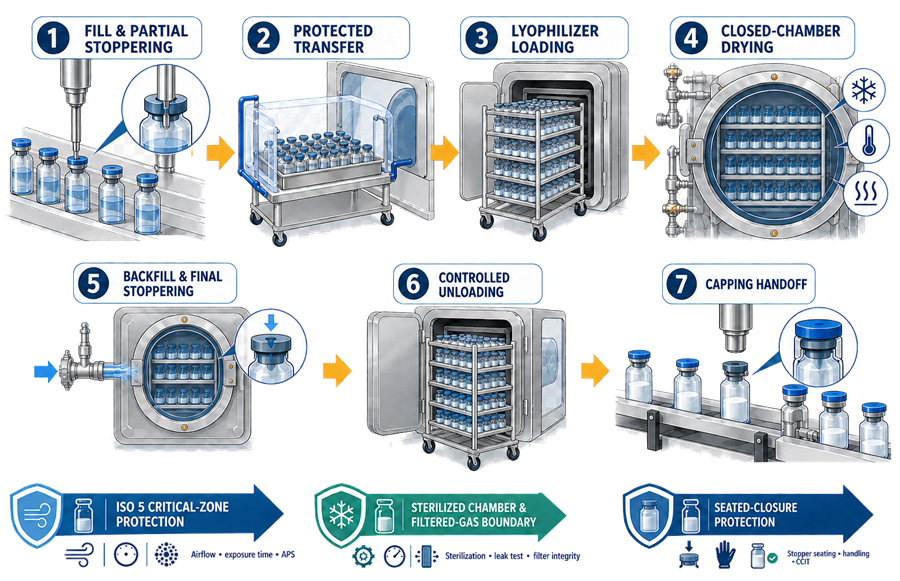
The sterile-protection strategy changes as the container moves through these states. Qualification must demonstrate that there is no uncontrolled gap between environmental protection, chamber protection, and final mechanical closure.
Regulatory and technical basis
The interface is governed through existing CGMP requirements rather than a dedicated United States regulation for lyophilizer loading.
Relevant requirements include:
- 21 CFR 211.42 for facility design and defined areas preventing contamination.
- 21 CFR 211.63 for suitable equipment design, size, and location.
- 21 CFR 211.67 for equipment cleaning and maintenance.
- 21 CFR 211.68 for automatic, mechanical, and electronic equipment.
- 21 CFR 211.100 for written production and process-control procedures.
- 21 CFR 211.113 for prevention of microbiological contamination and validation of aseptic processes.
FDA’s Sterile Drug Products Produced by Aseptic Processing guidance addresses critical-area protection, equipment suitability, interventions, environmental monitoring, and aseptic process simulation.
FDA’s Lyophilization of Parenteral inspection guide discusses protection of unsealed vials during transportation and loading and the representation of filling, transportation, loading, and stoppering activities in media fills.
For facilities applying EU requirements, EU GMP Annex 1 provides specific expectations for lyophilizer sterilization, leak testing, transfer of partially stoppered vials, loading patterns, barrier protection, sterile utensils, and unloading where containers remain unsealed.
Interface configurations
Manual loading
Manual systems may use trays, mobile unidirectional-airflow carts, portable transfer systems, or protected paths between the filling line and lyophilizer.
The qualification challenge is not limited to the cart or transfer device. It includes:
- Transfer from the filling machine.
- Operator movement.
- Tray handling.
- Door opening.
- Loading of each shelf.
- Removal of tray bottoms or loading aids.
- Movement of equipment through the airflow.
- Door closure.
- Recovery from interruptions.
- Post-cycle unloading.
Manual loading increases reliance on operator technique, exposure-time control, airflow protection, and aseptic process simulation.
RABS-supported transfer
A RABS configuration may protect filling and partial stoppering while requiring transfer through an adjacent critical zone or protected loading path.
The design should define:
- RABS opening and door controls.
- Transfer-path classification.
- Airflow direction.
- Interaction between filling-line and loading-zone airflow.
- Operator separation.
- Permitted interventions.
- Environmental-monitoring locations.
- Lyophilizer-door effects.
Opening a chamber door, moving trays, or positioning a transfer device can alter airflow around exposed vials. Static airflow evidence is insufficient.
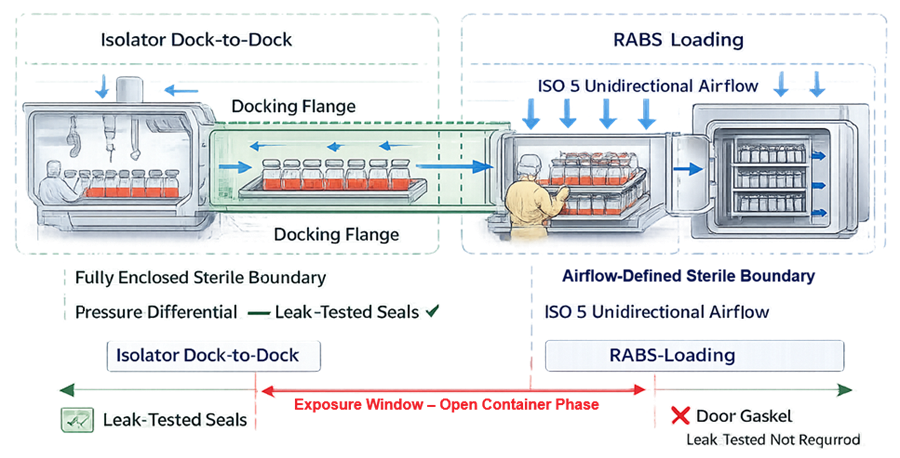
Isolator-integrated transfer
An isolator may be directly docked to the lyophilizer or connected through an automated loading and unloading system.
The interface may include:
- Docking flange.
- Chamber door.
- Isolator door.
- Transfer tunnel.
- Moving shelves or loading plates.
- Mousehole or door seals.
- Pressure-control boundary.
- Bio-decontamination boundary.
- Automated loading mechanism.
- Control-system handshakes.
An integrated isolator does not automatically create a continuously sterile boundary. Seal integrity, decontamination coverage, chamber sterilization, pressure control, transfer sequencing, and failure states require documented verification.
Prerequisites for interface qualification
Interface qualification should not begin until the contributing systems have reached an appropriate state of readiness. Prerequisites normally include:
- Approved system requirements and interface boundaries.
- Qualified filling line.
- Qualified lyophilizer.
- Qualified RABS, isolator, or protected transfer system.
- Approved chamber sterilization cycle.
- Qualified sterile vent and backfill-gas systems.
- Approved cleaning and bio-decontamination procedures.
- Qualified stopper feeding and partial-insertion system.
- Qualified lyophilizer stoppering mechanism.
- Qualified capping system.
- Calibrated instruments.
- Validated computerized functions.
- Approved container and stopper configuration.
- Approved loading pattern.
- Trained operators.
- Approved environmental-monitoring strategy.
- Defined aseptic process simulation strategy.
The lyophilization system qualification establishes chamber, shelf, vacuum, condenser, stoppering, instrumentation, alarm, and control-system capability. Interface qualification then demonstrates that those functions operate correctly with the filling line, barrier system, transfer mechanism, container configuration, and aseptic process.
Design qualification and risk assessment
Design Qualification should confirm that the interface can maintain protection throughout all container states and operating conditions.
The assessment should address:
- Distance between filling and loading.
- Maximum number of exposed vials.
- Maximum transfer and loading time.
- Manual versus automated loading.
- Tray and loading-frame design.
- Partially inserted stopper stability.
- Vial tipping and breakage.
- Airflow obstructions.
- Door opening and closing.
- Chamber venting during loading.
- Pressure relationships.
- Transfer-device sterilization or disinfection.
- Chamber cleaning and sterilization.
- Docking-seal design.
- Sterile gas filtration.
- Final stoppering.
- Unloading and capping transfer.
- Normal and corrective interventions.
- Failure detection and recovery.
- Electronic records and interface signals.
The risk assessment should distinguish:
- Microbial-contamination risk.
- Particulate-contamination risk.
- Container and stopper mechanical risk.
- Product-quality risk.
- Cross-contamination risk.
- Incorrect loading or batch identity.
- Automation and data-integrity risk.
- Operator-dependent risk.
Worst-case conditions should be based on the actual failure mechanism. Maximum batch size may create the longest exposure, while a minimum load may present a different airflow, pressure, or mechanical challenge.
Partial stoppering and container stability
Lyophilization stoppers are inserted to a defined intermediate position that permits vapor flow from the vial during drying. Qualification should demonstrate:
- Correct stopper orientation.
- Reproducible partial-insertion depth.
- Acceptable stopper-height distribution.
- Absence of over-insertion.
- Absence of loose or tilted stoppers.
- Stability during accumulation and transfer.
- Stability during vibration and indexing.
- Compatibility with the vial finish.
- Compatibility with chamber stoppering.
- Detection and rejection of missing or improperly positioned stoppers.
The qualification should represent applicable variation in:
- Vial dimensions.
- Stopper dimensions and formulation.
- Component lots.
- Filling-line speed.
- Stoppering force.
- Transfer vibration.
- Tray movement.
- Maximum waiting time.
- Environmental conditions.
A partially inserted stopper should not be treated as an established microbial seal. It may reduce direct exposure but does not replace qualified environmental or barrier protection.
Open-container exposure and time control
Several different time intervals may contribute to the total unsealed exposure:
- End of filling to partial stoppering.
- Partial stoppering to tray completion.
- Accumulation before transfer.
- Transfer to the lyophilizer.
- Loading.
- Loading interruption.
- Door-open time.
- Delay before chamber isolation.
- Post-cycle unloading when final stopper seating is incomplete or uncertain.
- Transfer time before capping.
The most direct environmental-exposure period extends from partial stoppering through protected accumulation, transfer, lyophilizer loading, and chamber-door closure. The illustration represents this pre-cycle open-container exposure window rather than the complete lyophilization–aseptic filling interface.
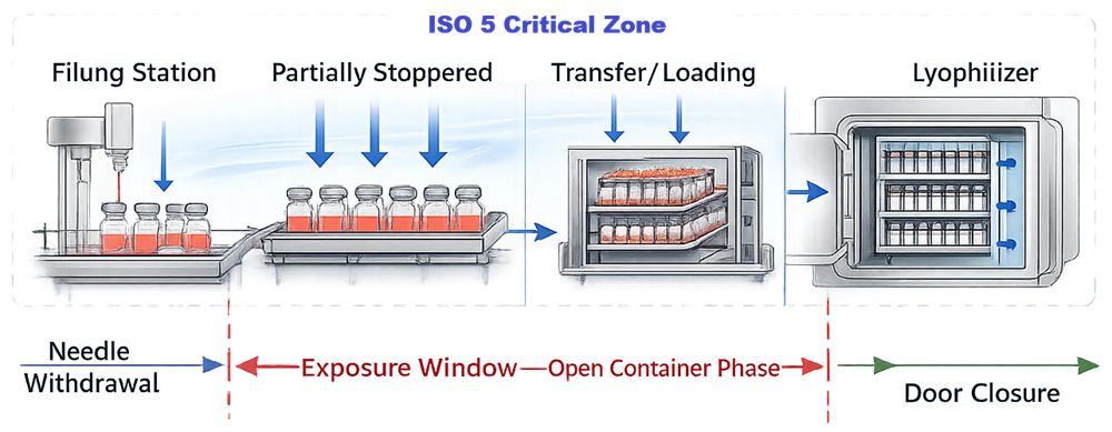
The protocol should define each controlled interval rather than using one poorly defined “lyophilizer loading time.”
Exposure limits should be supported by:
- Commercial batch size.
- Maximum loading pattern.
- Filling and transfer speeds.
- Manual handling time.
- Expected minor stops.
- Intervention duration.
- APS results.
- Environmental-control capability.
- Historical operating data, where applicable.
Limits should be incorporated into operating procedures, batch records, recipes, alarms, and deviation criteria.
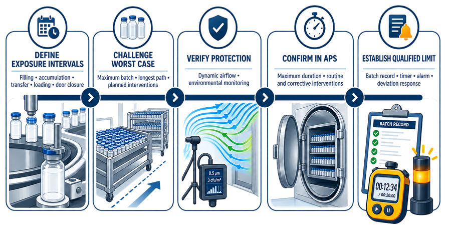
Establishing the exposure limit requires more than timing a routine loading operation. The study should define the contributing intervals, challenge justified worst-case conditions, verify environmental protection, represent the conditions in APS, and convert the resulting limit into an enforceable routine control.
Airflow visualization and environmental qualification
Airflow visualization studies should demonstrate protection under representative dynamic conditions.
Studies should include, as applicable:
- Partially stoppered vials leaving the filling machine.
- Tray formation and accumulation.
- Loading-device positioning.
- Movement of carts or trays.
- Operator approach and withdrawal.
- Lyophilizer-door opening.
- Loading of upper, middle, and lower shelves.
- Movement of automated loading equipment.
- Maximum equipment occupancy.
- Normal interventions.
- Corrective interventions.
- Minor stops.
- Removal of loading aids.
- Door closure.
The study should determine whether:
- First air reaches exposed containers.
- Equipment creates turbulence or airflow shadowing.
- Door movement causes reverse flow.
- Transfer devices disrupt returns.
- Operator movement affects exposed vials.
- Chamber airflow draws contamination toward the load.
- Conditions recover within the established time.
Smoke visualization should be coordinated with viable and nonviable environmental monitoring for aseptic filling. Smoke alone does not establish microbiological control. Monitoring locations should reflect the loading configuration and should not interfere with airflow or create additional risk to exposed containers.
Chamber sterilization and sterile-boundary control
The chamber, shelves, stoppering components, loading accessories, and relevant product-exposure surfaces should be subjected to qualified cleaning and sterilization processes. The control strategy should define:
- Cleaning requirements.
- Chamber sterilization method.
- Sterilization frequency.
- Permitted sterile hold time.
- Post-sterilization protection.
- Chamber leak-test frequency.
- Maximum acceptable leak rate.
- Sterile vent-filter control.
- Sterile backfill-gas filtration.
- Filter sterilization and integrity testing.
- Door and docking-seal verification.
- Response to failed sterilization or leak testing.
Chamber qualification should not be confused with interface qualification. However, interface release depends on evidence that the chamber and associated sterile pathways remain in the required state when the exposed load is introduced.
A chamber leak test demonstrates pressure-boundary integrity under the tested conditions. It does not independently demonstrate chamber sterility, vent-filter integrity, or absence of contamination during loading.
Loading-pattern and transfer qualification
The approved loading pattern should be documented by batch size, shelf allocation, vial arrangement, and use of trays or loading aids. Qualification should challenge:
- Minimum and maximum loads.
- Longest loading duration.
- Upper and lower shelves.
- First and last loaded rows.
- Maximum tray weight.
- Vial accumulation.
- Tray or loading-plate transitions.
- Misalignment.
- Vial tipping.
- Glass breakage.
- Stopper displacement.
- Partial mechanical obstruction.
- Maximum permitted loading-device travel.
- Transfer interruption.
- Recovery after a controlled stop.
Loading equipment should not damage vials, alter stopper position, generate unacceptable particles, or create an unqualified airflow disturbance.
Trays, push bars, loading plates, guides, and utensils should be:
- Identified.
- Cleanable.
- Sterilizable where required.
- Inspected before use.
- Maintained under change control.
- Checked for distortion or damage.
A tray or loading plate that changes thermal contact can also affect freeze-drying performance. Its use should be coordinated with product-cycle development and validation.
Automation and control-system integration
Modern systems may coordinate the filling line, barrier system, automatic loading and unloading system, chamber doors, shelves, vacuum controls, and capping transfer through multiple control systems. Qualification should verify interface signals such as:
- Filling complete.
- Batch and recipe identity.
- Load available.
- Lyophilizer ready to load.
- Chamber sterilization complete.
- Leak test accepted.
- Barrier decontamination complete.
- Door permissive.
- Loading system aligned.
- Shelf position confirmed.
- Load complete.
- Door closed and locked.
- Cycle permitted to start.
- Stoppering complete.
- Unloading permitted.
- Transfer to capping accepted.
Failure testing should address:
- Loss of communication.
- Conflicting equipment states.
- Incorrect recipe.
- Incorrect batch identity.
- Door or docking-seal failure.
- Loading-device misalignment.
- Sensor failure.
- Partial load interruption.
- Power interruption.
- Emergency stop.
- Failed chamber leak test.
- Failed sterilization cycle.
- Failed vent-filter integrity test.
- Incomplete stoppering.
- Unloading-system failure.
- Data-collection interruption.
Recovery should return the system to a defined state without concealing the original failure or creating an uncontrolled aseptic exposure.
Electronic controls should include, as applicable:
- Role-based access.
- Recipe protection.
- Audit trails.
- Alarm records.
- Event chronology.
- Secure time synchronization.
- Data storage and retrieval.
- Interface-data verification.
- Backup and recovery.
- Configuration control.
Operational qualification of the interface
Operational Qualification should challenge interface functions across their approved ranges independently of commercial product performance.
The OQ should address:
- Transfer and loading sequences.
- Manual and automatic operating modes.
- Minimum and maximum equipment speeds.
- Door and docking functions.
- Loading-device alignment.
- Shelf-position confirmation.
- Stopper-position detection.
- Container and tray sensors.
- Exposure timers.
- Alarms and interlocks.
- Pressure differentials.
- Sterile vent and backfill sequences.
- Final stoppering.
- Unloading.
- Communication failures.
- Power-loss response.
- Emergency stops.
- Controlled restart and recovery.
- Electronic record generation.
Surrogate vials, stoppers, and loads may be used when they adequately represent the mechanical and operational characteristics of the commercial configuration.
Testing should confirm both successful operation and correct rejection or safe-state response when required conditions are not met.
Performance qualification
Performance Qualification should demonstrate integrated, reproducible operation with representative production configurations. PQ should include, as applicable:
- Approved vial and stopper combinations.
- Representative component lots.
- Minimum and maximum batch sizes.
- Approved loading patterns.
- Routine operating speeds.
- Longest transfer and loading duration.
- Qualified operators.
- Representative interventions.
- Maximum permitted waiting periods.
- Final stoppering.
- Unloading and transfer to capping.
- Complete batch documentation.
Acceptance criteria may address:
- Exposure time.
- Loading completeness.
- Vial breakage.
- Vial tipping.
- Stopper displacement.
- Partial-stopper height.
- Final-stopper seating.
- Container rejection.
- Alarm occurrence.
- Interface-data completeness.
- Environmental conditions.
- Successful completion of required chamber and filter checks.
Interface PQ should be coordinated with the fill-line qualification lifecycle and product-specific lyophilization validation without treating them as interchangeable studies.
Aseptic process simulation
The aseptic process simulation should represent the aseptic manipulations associated with lyophilized product manufacture.
Applicable activities include:
- Media filling.
- Partial stoppering.
- Accumulation.
- Transfer.
- Loading.
- Maximum justified exposure.
- Representative loading interruptions.
- Routine and corrective interventions.
- Chamber-door closure.
- Defined chamber hold.
- Final stoppering.
- Unloading.
- Transfer to capping.
The APS design should preserve microbial recovery. A complete freeze-drying cycle may expose microorganisms to freezing, vacuum, or desiccation conditions that reduce recovery and obscure the purpose of the simulation.
The simulation may therefore use an approved approach that represents the aseptic loading, chamber hold, stoppering, and unloading sequence without subjecting the medium to conditions that invalidate microbial-growth detection.
The rationale should define:
- Which commercial steps are simulated.
- Which steps are modified or omitted.
- How the maximum exposure is represented.
- How all units remain recoverable.
- How the chamber and loading pattern are represented.
- How interventions are distributed.
- How post-cycle handling is included.
APS complements mechanical and functional qualification. It does not replace airflow visualization, chamber sterilization validation, filter-integrity control, alarm testing, or closure qualification.
See media fill and aseptic process simulation for the broader APS lifecycle.
Final stoppering and closure control
Final stoppering normally occurs within the closed lyophilizer by raising the shelves and compressing the stoppers into the vial finish under vacuum or controlled gas backfill. Qualification should verify:
- Shelf travel.
- Stoppering force.
- Parallelism and alignment.
- Stopper seating across all shelf positions.
- Backfill pressure.
- Gas quality.
- Absence of stopper pop-up.
- Absence of tilted stoppers.
- Absence of vial tipping or breakage.
- Correct cycle sequencing.
- Detection of incomplete stoppering.
Final stopper seating should be evaluated across representative and worst-case vial and stopper configurations.
After unloading, controls should maintain closure position until capping. Conveyor shock, vibration, accumulation, and delay before capping should not cause stopper displacement.
The relationship among stoppering, capping, and closure integrity should be coordinated with:
A correct measured stopper height is a process-control result. It is not automatically equivalent to demonstrated container-closure integrity.
Routine batch readiness and review
Before loading begins, batch-readiness verification should confirm:
- Correct lyophilizer and product recipe.
- Approved chamber-cleaning status.
- Successful sterilization status.
- Acceptable chamber leak-test status.
- Vent and backfill-filter status.
- Barrier or isolator readiness.
- Loading-system readiness.
- Calibration status.
- Approved loading pattern.
- Availability of sterile trays and utensils.
- Environmental-monitoring readiness.
- Correct container and stopper configuration.
- Availability of capping capacity.
- Trained personnel.
- Absence of unresolved critical alarms.
Batch review should include:
- Filling completion and partial-stopper results.
- Transfer and loading times.
- Door-open duration.
- Loading-system events.
- Chamber leak-test results.
- Filter-integrity results.
- Sterilization-cycle records.
- Alarms and interventions.
- Environmental-monitoring results.
- Stoppering-cycle data.
- Unloading and capping times.
- Vial and stopper rejects.
- Deviations and investigations.
- Audit-trail review where required.
Deviations and failure response
Procedures should define responses to:
- Loading delay.
- Loss of critical-zone protection.
- Transfer-cart failure.
- RABS or isolator alarm.
- Door or docking failure.
- Damaged sterile utensil.
- Tray misalignment.
- Vial breakage.
- Stopper displacement.
- Loading-system jam.
- Power interruption.
- Communication failure.
- Chamber leak-test failure.
- Sterilization-cycle failure.
- Vent or backfill-filter failure.
- Vacuum loss.
- Incomplete final stoppering.
- Stopper pop-up.
- Extended unloading or capping delay.
The investigation should establish:
- Which units were potentially affected.
- Their location within the load.
- Container state when the event occurred.
- Duration of exposure.
- Environmental conditions.
- Whether the chamber boundary remained intact.
- Whether product segregation is possible.
- Whether APS and qualification evidence cover the event.
- Whether additional inspection or testing is justified.
- Whether the event indicates a recurring system weakness.
Restarting the equipment or completing a subsequent successful cycle does not invalidate the original deviation.
Continued verification and periodic review
Routine monitoring should trend:
- Transfer time.
- Loading time.
- Door-open time.
- Loading interruptions.
- Vial tipping and breakage.
- Stopper-position rejects.
- Incomplete stoppering.
- Chamber leak rates.
- Sterilization-cycle deviations.
- Filter-integrity failures.
- Barrier and airflow alarms.
- Environmental-monitoring results.
- Loading-system failures.
- Interventions.
- Capping delays.
- APS results.
- Maintenance and calibration history.
Periodic review should determine whether:
- Interface boundaries remain accurate.
- Approved loading patterns remain current.
- Exposure limits remain representative.
- Operators continue to follow qualified practices.
- Chamber and filter controls remain effective.
- Automated interfaces remain in their validated configuration.
- Alarm and intervention trends remain acceptable.
- Changes were properly assessed.
- Requalification or APS modification is required.
Change control and requalification
Potential triggers include:
- New vial or stopper.
- Revised partial-stopper position.
- New batch size or loading pattern.
- Increased filling or loading speed.
- New tray or loading plate.
- Transfer-cart modification.
- RABS or isolator modification.
- Barrier bio-decontamination change.
- Lyophilizer-door modification.
- Docking-seal change.
- Automated loading-system modification.
- Robot-path or motion change.
- Software or recipe change.
- Interface-signal change.
- Chamber-sterilization change.
- Vent or backfill-filter change.
- Change in sterile-gas supply.
- Stoppering-system adjustment.
- Capping-line relocation.
- Increased exposure or hold time.
- Significant HVAC work.
- Repeated loading, stopper, or environmental failures.
Each change should undergo a documented change-control impact assessment.
Possible outcomes include:
- Documentation update.
- Engineering verification.
- Targeted alarm or interlock testing.
- Airflow visualization.
- Exposure-time verification.
- Loading or stoppering studies.
- APS inclusion.
- Targeted interface requalification.
- Comprehensive interface requalification.
The scope should follow the site’s risk-based requalification process.
Common deficiencies
Common deficiencies include:
- Defining the interface as transfer only.
- Ending the interface boundary at chamber-door closure.
- Treating partial stoppering as a microbial seal.
- Assuming that a qualified filling line and lyophilizer automatically qualify their interface.
- Using static airflow studies for dynamic loading.
- Establishing one undefined total exposure time.
- Failing to challenge loading interruptions.
- Omitting unloading and transfer to capping.
- Excluding loading or stoppering from APS.
- Running an APS cycle that reduces microbial recovery without adequate justification.
- Failing to qualify loading trays and utensils.
- Ignoring sterile vent and backfill pathways.
- Failing to test equipment handshakes and communication failures.
- Treating chamber leak testing as proof of chamber sterility.
- Failing to verify final stoppering across the shelf area.
- Treating stopper height as direct proof of closure integrity.
- Inadequate review of alarms, interventions, and loading-time trends.
- Failing to reassess the interface after equipment, software, component, or loading-pattern changes.
Conclusion
The lyophilization–aseptic filling interface is an integrated aseptic-processing segment extending from partial stoppering through protected transfer, chamber loading, controlled freeze-drying, final stoppering, unloading, and transfer toward capping.
A defensible qualification program combines defined system boundaries, design review, airflow visualization, exposure-time control, chamber and filter readiness, loading-pattern qualification, automation testing, performance qualification, APS, closure verification, deviation control, continued monitoring, and change management.
The filling line and lyophilizer may be qualified separately. Sterility assurance depends on demonstrating that their interface functions as one controlled process.