

Steam Sterilizer Qualification: IQ, OQ, and PQ
Steam sterilizer qualification establishes documented evidence that the installed sterilizer, its supporting utilities, controls, instruments, recipes, and defined load configurations can consistently deliver an approved moist-heat sterilization process.
Qualification is broader than temperature mapping and cannot begin with loaded performance runs. It starts with intended use, requirements, design decisions, risk assessment, commissioning, and verification of the installed configuration. It then progresses through functional challenges, air-removal and chamber-integrity testing where applicable, empty-chamber thermal studies, loaded heat-penetration studies, microbiological challenges, deviation resolution, and formal release.
The document sequence may be called DQ, IQ, OQ, and PQ or may be organized through integrated commissioning and qualification protocols. The labels are secondary to the evidence. The program must demonstrate that:
- Requirements and design inputs are defined and approved
- The installed system matches the accepted design
- Critical functions operate throughout their required ranges
- Alarms, interlocks, recipes, records, and failure responses work as intended
- Air is adequately removed where required by the cycle design
- Chamber leakage remains within defined limits
- Empty-chamber thermal conditions are controlled
- Defined loads receive adequate and reproducible heat penetration
- The microbiological challenge is appropriate and successfully inactivated
- Product, component, package, and load requirements remain acceptable
- Deviations and residual risks are resolved before release
- Requirements, risks, tests, results, and conclusions remain traceable
The principles and cycle types underlying these activities are addressed in Moist Heat Sterilization Principles and Cycle Types.
Purpose and Scope
This article addresses initial qualification of pharmaceutical and biotechnology steam sterilizers used for:
- Terminal sterilization of aqueous drug products
- Sterilization of equipment parts and components
- Sterilization of porous or wrapped loads
- Sterilization of laboratory or manufacturing supplies
- Sterilization of filters, hoses, vessels, and assemblies
- Bio-decontamination or waste-treatment cycles where GMP qualification is required
- Other defined moist-heat applications using chamber sterilizers
It covers:
- Intended use and system boundaries
- User and process requirements
- Design review and design qualification
- Commissioning and supplier-documentation leverage
- Qualification planning and readiness
- Installation Qualification
- Control-system and data verification
- Operational Qualification
- Chamber leak testing
- Air-removal and Bowie-Dick-type testing where applicable
- Empty-chamber heat-distribution studies
- Performance Qualification
- Loaded heat distribution and penetration
- Biological-indicator challenges
- Product, load, and package evaluation
- Qualification deviations and repeat testing
- Requirements traceability
- Qualification reporting and release
Detailed development of load configurations and cycle parameters is addressed in Steam Sterilization Load and Cycle Development. Sensor selection, placement, data acquisition, cold-location analysis, and F₀ calculation are addressed in Steam Sterilization Temperature Mapping, Heat Distribution, and Penetration.
Requalification after changes, maintenance, failures, adverse trends, or periodic review is addressed in Requalification and Continued Verification.
Qualification Lifecycle
Steam sterilizer qualification is an evidence sequence extending from approved requirements through formal release.
A typical lifecycle includes:
- Define intended use, system boundaries, products, cycles, and loads.
- Develop and approve user, process, quality, automation, and data requirements.
- Evaluate process and equipment risks.
- Review the proposed design against approved requirements.
- Execute supplier testing, factory acceptance testing, installation, commissioning, and site acceptance testing.
- Assess which supplier and commissioning evidence can be used in qualification.
- Confirm qualification readiness.
- Verify the installed configuration through IQ.
- Verify controls, operating ranges, alarms, failures, chamber integrity, air removal, and empty-chamber performance through OQ.
- Confirm performance with approved representative and worst-case loads through PQ.
- Resolve deviations, complete traceability, and approve the qualification report.
- Release the sterilizer, recipes, and load configurations for defined routine uses.
- Maintain the qualified state through calibration, maintenance, monitoring, change control, periodic review, and requalification.
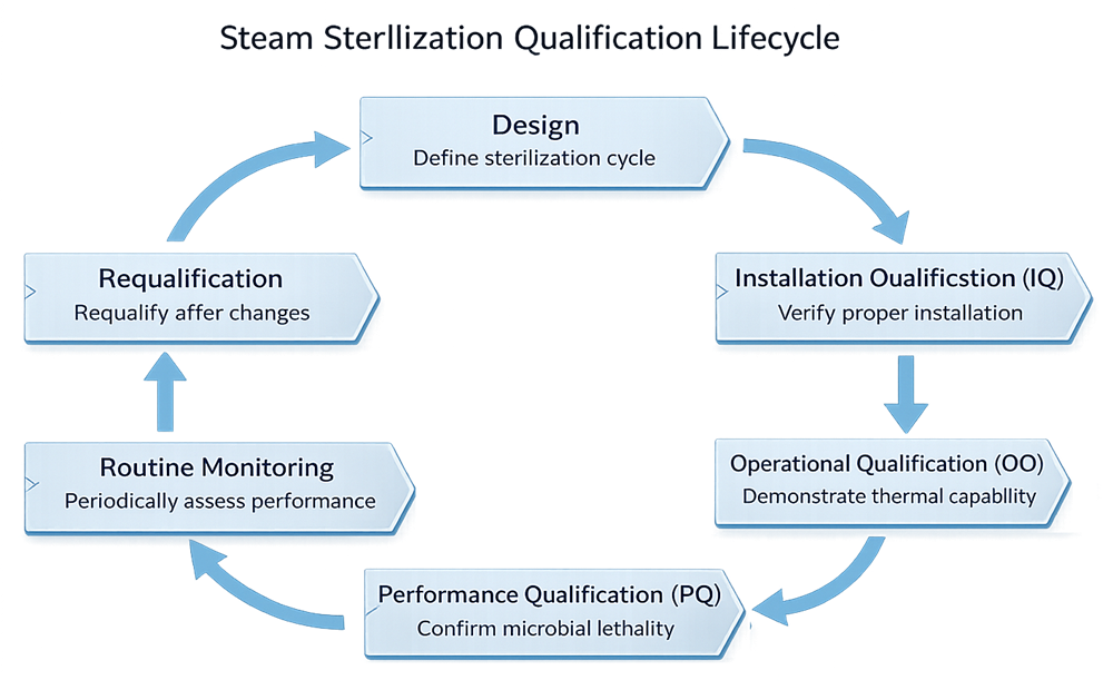
The lifecycle diagram shows the relationship among design, IQ, OQ, PQ, routine monitoring, and requalification. Requirements, commissioning, traceability, deviation resolution, and formal release should be described in the surrounding text because they are essential lifecycle controls even if they are not shown as separate boxes in the illustration.
Qualification stages may overlap when an integrated approach is controlled and justified. For example, a commissioning loop check may provide IQ or OQ evidence, and a loaded heat-distribution study may support both equipment performance and cycle validation. Overlap does not eliminate the need to identify the purpose, acceptance criteria, configuration, and approval status of the evidence.
Intended Use and Qualification Boundary
The qualification boundary should be defined before protocols are written.
The boundary may include:
- Sterilizer chamber
- Jacket
- Door or doors
- Door seals and locking mechanisms
- Steam inlet and distribution arrangement
- Chamber drain, drain strainer, and temperature sensor
- Air-removal system
- Vacuum pump or ejector
- Air-admission and sterile-air filters
- Condensate-removal devices and traps
- Cooling-water or cooling-air systems
- Compressed air used for pressure support or control
- Load carts, racks, shelves, baskets, and transfer systems
- Control panel and programmable controller
- Human-machine interface
- Cycle recipes and configurable parameters
- Control and monitoring instruments
- Batch or cycle-record generation
- Printer, historian, server, or electronic-record interface
- Utility interfaces
- Safety systems
- Validation ports and chamber penetrations
- Supporting software and firmware
The sterilizer boundary should be distinguished from supporting-utility boundaries. A sterilizer may receive qualified clean steam, compressed air, water, cooling media, power, and drainage services without assuming ownership of the complete utility systems.
Qualification of the clean steam system is addressed separately in Clean Steam System Qualification, Monitoring, and Requalification. Successful clean steam qualification does not establish that steam is adequately distributed through a sterilizer load. Conversely, a successful sterilizer cycle does not qualify the clean steam generator or every distribution point.
The qualification program should identify whether it covers:
- One sterilizer or a group of nominally identical sterilizers
- One chamber size or multiple sizes
- One control-system version or several configurations
- One cycle type or multiple cycle types
- Equipment qualification only
- Specific load and recipe qualification
- Load-family qualification
- Product sterilization-process validation
- Routine-use release requirements
Evidence from one sterilizer should not be transferred automatically to another. Equipment equivalence must be demonstrated using design, construction, controls, instruments, utilities, chamber geometry, load accessories, operating ranges, and performance evidence.
Requirements and Design Inputs
Qualification begins with approved requirements, not with protocol execution.
The URS for GMP Facilities, Utilities, and Equipment should define what the sterilizer must accomplish for its intended use. Requirements should be clear, testable, traceable, and established early enough to influence design and procurement.
Intended-Use Requirements
Requirements should identify:
- Materials, products, equipment, components, or waste to be processed
- Terminal sterilization, component sterilization, or other intended applications
- Required cycle types
- Expected load families
- Minimum and maximum load quantities
- Container and package types
- Required chamber capacity
- Required throughput
- Loading and unloading arrangements
- Single-door or pass-through configuration
- Clean-side and dirty-side relationships
- Required operating schedule and availability
- Redundancy or recovery expectations
Process Requirements
Process requirements may address:
- Temperature ranges
- Pressure ranges
- Exposure-time capability
- Vacuum depth and pulse capability
- Steam-flush or gravity-displacement capability
- Air-overpressure capability
- Heating and cooling rates
- Cooling-medium control
- Drying capability
- Required F₀ calculation or display
- Product-temperature monitoring
- Maximum allowable product or package exposure
- Required control and monitoring sensors
- Cycle-abort conditions
- Permitted operating envelope
The URS should define required capability without presenting undeveloped cycle parameters as established validation acceptance criteria. Final recipes and limits may be established through approved Steam Sterilization Load and Cycle Development.
Mechanical and Hygienic Design Requirements
Requirements may include:
- Chamber material and surface finish
- Jacket construction
- Drainability
- Chamber slope
- Door construction
- Door-seal design
- Prevention of simultaneous opening for pass-through units
- Chamber and jacket insulation
- Cleanability
- Access for inspection and maintenance
- Suitable piping materials and fabrication
- Condensate removal
- Sterile-air filtration
- Load-cart and rack construction
- Validation access ports
- Prevention of contamination transfer between chamber sides
- Pressure-vessel and safety requirements
Utility Requirements
Required utilities may include:
- Clean steam or other approved steam supply
- Plant steam for the jacket
- Purified water or other cooling water
- Compressed air
- Sterile filtered air
- Instrument air
- Vacuum
- Electrical power
- Drainage
- Ventilation or heat removal
- Network or data services
The requirements should define needed quality, capacity, pressure, flow, temperature, and availability at the sterilizer interface.
Controls and Data Requirements
Requirements should address:
- Automatic cycle sequencing
- Manual and service modes
- Recipe creation, approval, selection, and revision
- Adjustable and protected parameters
- User roles and access levels
- Alarm generation and acknowledgement
- Interlocks and permissives
- Cycle interruption and abort
- Power-loss response
- Restart and recovery
- Sensor-failure response
- Control and monitoring channels
- Independent recording where required
- Cycle-record content
- Time synchronization
- Data retention
- Backup and recovery
- Audit trail where applicable
- Electronic signatures where applicable
- Interface with historians, manufacturing systems, or building systems
- Report generation and review
A Part 11 assessment should determine whether the sterilizer creates or maintains electronic records required by applicable predicate rules and which controls are necessary for those records.
Risk Assessment and Qualification Strategy
Risk assessment should identify specific sterilizer and process failure modes rather than assign one general risk rating to the complete system.
Potential failure modes include:
- Inadequate air removal
- Chamber leakage
- Non-condensable gases
- Wet or superheated steam
- Inadequate condensate drainage
- Low steam pressure
- Loss of vacuum
- Door-seal failure
- Simultaneous door opening
- Incorrect recipe selection
- Unauthorized parameter changes
- Incorrect exposure-start logic
- Control-sensor failure
- Monitoring-sensor failure
- Incomplete cycle record
- Loss of data
- Incorrect time synchronization
- Inadequate chamber distribution
- Inadequate load penetration
- Excessive product exposure
- Inadequate cooling
- Container breakage
- Closure movement
- Wet loads
- Sterile-air-filter failure
- Utility interruption
- Failure to detect or abort an unacceptable cycle
The risk assessment should connect each significant failure to:
- Design prevention
- Detection method
- Alarm or interlock
- Qualification test
- Routine monitoring
- Procedural response
- Maintenance or calibration control
- Requalification trigger
The qualification strategy should define:
- System and protocol boundaries
- Applicable requirements and standards
- Roles and approval responsibilities
- Supplier and commissioning evidence to be leveraged
- IQ, OQ, and PQ scope
- Cycle types requiring qualification
- Load families and representative loads
- Worst-case conditions
- Required thermal and microbiological studies
- Required number of runs
- Acceptance criteria
- Deviation and retest rules
- Traceability method
- Release criteria
- Routine monitoring baseline
- Requalification requirements
The general principles for focusing qualification on risks, functions, and controls are addressed in Risk-Based Validation Approach for GMP Systems.
Design Review and Design Qualification
Design Qualification should determine whether the proposed sterilizer and its supporting systems are capable of satisfying approved requirements.
The review should consider:
- Chamber size and geometry
- Loading arrangement
- Door configuration
- Steam-inlet location
- Drain location
- Air-removal method
- Vacuum-system capacity
- Condensate drainage
- Jacket design
- Cooling method
- Sterile-air admission
- Control and monitoring sensors
- Sensor independence
- Instrument ranges and accuracy
- Control-system architecture
- Recipe security
- Data and report architecture
- Utility capacity
- Maintenance and calibration access
- Validation access
- Clean-side and dirty-side controls
- Facility interfaces
- Safety requirements
- Expected load and cycle envelope
- Future expansion or additional load types
Design review should include manufacturing, engineering, validation, quality, microbiology, automation, maintenance, metrology, safety, and process-development personnel as applicable.
Unresolved design issues should be documented and closed before they can invalidate installation or operational testing. Approval of the vendor’s standard design does not demonstrate that the system is suitable for the site’s products, loads, facility, utilities, or data requirements.
Supplier Testing, Commissioning, and Qualification Leverage
Supplier, factory, and commissioning activities can produce valuable evidence. Useful activities may include:
- Design-document review
- Factory acceptance testing
- Software and sequence testing
- Instrument loop checks
- Alarm and interlock testing
- Chamber pressure testing
- Door-operation testing
- Vacuum-system testing
- Utility-demand testing
- Recipe verification
- Cycle-record review
- Installation inspection
- Site acceptance testing
- Start-up and control tuning
- Engineering empty-chamber runs
- Preliminary loaded studies
Commissioning evidence may be used in qualification when it is:
- Planned against approved requirements or specifications
- Executed on an identified configuration
- Performed using suitable and calibrated instruments
- Recorded contemporaneously
- Supported by actual results
- Reviewed for discrepancies and deviations
- Traceable to the installed system
- Protected from uncontrolled change
- Formally assessed and accepted for its GMP purpose
A signed commissioning checklist containing only “pass” entries may be inadequate when qualification relies on the underlying measurements, challenge conditions, or observations.
Factory evidence should be assessed for differences between the factory and installed configurations. Relevant differences may include:
- Chamber accessories
- Utility media
- Control-system version
- Instrument ranges
- Recipe configuration
- Network architecture
- Data interfaces
- Load carts or racks
- Door orientation
- Site-specific alarms
- Site operating conditions
Tests should be repeated at the site when transportation, reassembly, installation, site utilities, configuration changes, or operating environment can affect the conclusion.
Qualification Readiness
Formal qualification should begin only after the sterilizer has reached a controlled and sufficiently stable configuration.
Readiness review should confirm, as applicable:
- Approved URS and design documents
- Approved qualification plan
- Defined system boundary
- Current P&IDs, wiring diagrams, and control documents
- Completed equipment installation
- Completed start-up and commissioning
- Current hardware, software, firmware, and recipe baseline
- Completed critical punch-list items
- Defined disposition of remaining noncritical items
- Available qualified supporting utilities
- Completed initial calibration
- Available calibration standards
- Approved alarm and interlock list
- Available operating and maintenance procedures
- Available load and cycle-development evidence
- Approved protocol and acceptance criteria
- Available load items and accessories
- Available calibrated validation data-acquisition system
- Available biological indicators and laboratory support
- Trained operators and study personnel
- Defined deviation and sample-handling procedures
Qualification should not be used as the primary method for debugging an incomplete system. Engineering adjustments made during execution can change the tested configuration and require assessment or repetition of affected tests.
Installation Qualification
Installation Qualification establishes the controlled installed baseline against which operational and performance results are interpreted.
Equipment Identification and Configuration
IQ should verify:
- Manufacturer
- Model
- Serial number
- Asset number
- Chamber dimensions and volume
- Door configuration
- Pressure-vessel identification
- Major subsystem identification
- Load-cart and rack identification
- Installed hardware configuration
- Software and firmware versions
- Control-program version
- HMI version
- Recipe-management configuration
- Network and interface configuration
Mechanical Installation
Verification should address:
- Chamber and jacket construction
- Door and seal installation
- Door-locking mechanisms
- Steam inlet
- Chamber drain
- Drain strainer
- Vacuum-system components
- Air-admission components
- Sterile-air-filter housing
- Valves and actuators
- Steam traps and separators
- Piping materials and connections
- Insulation
- Supports
- Utility connection identification
- Accessibility for operation and maintenance
- Validation ports
- Load accessories
- Safety devices
- As-built drawings
For pass-through sterilizers, IQ should verify the physical arrangement and identification of the loading and unloading sides and the installed provisions supporting controlled door operation.
Utility Interfaces
IQ should document:
- Utility source
- Connection point
- Required quality
- Design pressure and temperature
- Instrumentation
- Isolation
- drainage
- Filtration
- Backflow prevention
- Available capacity
- Applicable qualification reference
Supporting utility certificates or qualification reports should be traceable to the sterilizer interface and current configuration.
Instrumentation and Calibration
IQ should verify:
- Instrument tag
- Manufacturer and model
- Serial number
- Location
- Function
- Range
- Accuracy requirement
- Resolution
- Calibration status
- Calibration range
- Calibration points
- Control or monitoring designation
- Data-record association
Calibration must cover the range used for qualification and routine decisions. Ambient-only calibration does not establish suitability for instruments used around steam-sterilization temperatures.
The relationship among chamber-control, chamber-monitoring, drain, jacket, pressure, load, and independent validation sensors should be documented.
Documentation
IQ documentation may include:
- Approved drawings
- Equipment specifications
- Material certificates
- Pressure-vessel documentation
- Weld records
- Surface-finish records
- Pressure and leak-test records
- Instrument data sheets
- Calibration certificates
- Electrical drawings
- Control narratives
- Software and configuration records
- Manuals
- Spare-parts lists
- Preventive-maintenance recommendations
- Safety documentation
- Supplier test records
- Commissioning records
Document availability alone is insufficient. The review should determine whether documents are complete, applicable to the installed equipment, and consistent with field conditions.
Control-System and Data Verification
Sterilizer controls should be verified as a GMP-relevant computerized application when they control critical parameters, calculate or report process results, manage recipes, generate batch records, or support load release.
Verification should address:
- User roles
- Login controls
- Password management
- Administrative access
- Recipe creation and approval
- Recipe revision
- Parameter limits
- Protection of critical setpoints
- Recipe identification on cycle records
- Automatic sequence logic
- Phase transitions
- Exposure-start and exposure-end logic
- F₀ calculation where used
- Alarm detection
- Alarm acknowledgement
- Interlocks and permissives
- Manual-mode restrictions
- Service-mode restrictions
- Aborted-cycle identification
- Power-loss behavior
- Restart and recovery
- Time and date
- Time synchronization
- Record completeness
- Printer or report output
- Electronic-data retention
- Audit trail where applicable
- Backup
- Restoration
- Interfaces
- Data export
- Protection against unauthorized alteration
Displayed values, recorded values, and values used by the control logic should be reconciled where they come from different sensors or data paths.
Calculated results should be verified using known inputs. This applies to F₀, exposure duration, pressure conversion, temperature averages, alarm delays, and other values used for acceptance or release.
Operational Qualification
Operational Qualification demonstrates that the installed sterilizer functions according to approved requirements throughout its defined operating ranges, modes, transitions, and credible failure conditions.
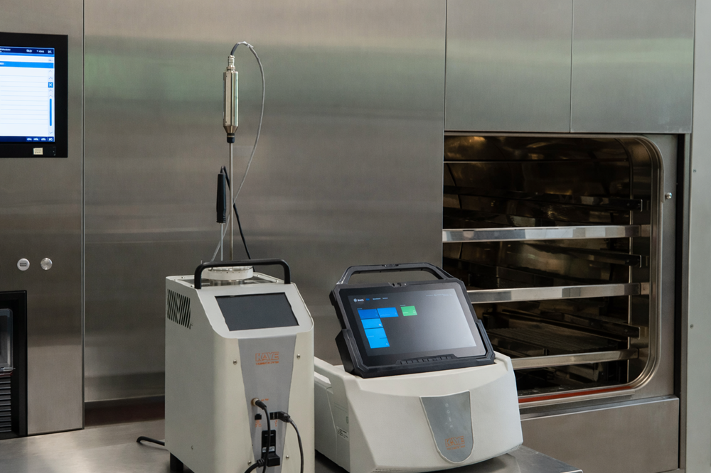
The independent temperature-mapping system provides thermal evidence separate from the sterilizer’s control and monitoring channels. Its configuration, thermocouples, calibration, channel assignments, sampling interval, clock, calculations, and raw electronic data must remain controlled.
OQ should not be limited to completion of successful empty-chamber cycles. It should challenge the equipment functions that establish, control, monitor, record, and protect the sterilization process.
Operating Sequences and Modes
Testing should address applicable:
- Start-up
- Preconditioning
- Air-removal pulses
- Steam admission
- Heating
- Equilibration
- Exposure
- Exhaust
- Cooling
- Drying
- Air admission
- Cycle completion
- Door release
- Shutdown
- Restart
- Manual operation
- Service mode
The verified sequence should match the approved control narrative and recipe configuration.
Alarms, Interlocks, and Failure Responses
Potential challenges include:
- Door not closed
- Door not locked
- Simultaneous-door request
- Low steam pressure
- High or low chamber temperature
- Excessive chamber pressure
- Vacuum failure
- Excessive evacuation time
- Temperature-sensor failure
- Pressure-sensor failure
- Drain-sensor failure
- Cooling-water failure
- Compressed-air failure
- Sterile-air-filter condition where monitored
- Power loss
- Communication loss
- Printer or record-generation failure
- Exposure deviation
- Excessive cycle time
- Aborted cycle
Testing should verify:
- Detection
- Alarm message
- Alarm priority where applicable
- Delay time
- Automatic system response
- Operator response
- Cycle status
- Record annotation
- Recovery requirements
- Prevention of inappropriate load release
Not every credible failure must be created destructively. Simulation, forced input, controlled disconnection, configuration tools, or documented supplier evidence may be used when the method adequately verifies the required response and does not create unacceptable risk.
Chamber Leak Testing
A chamber leak test evaluates the ability of an evacuated sterilizer chamber and associated system to maintain vacuum within a defined pressure-rise or leak-rate limit.
The test is particularly relevant to dynamic-air-removal sterilizers because air leakage during vacuum phases can impair air removal, steam contact, and reproducibility.
The protocol should define:
- Required starting vacuum
- Stabilization period
- Test duration
- Pressure measurement method
- Calculation method
- Temperature considerations
- Acceptance limit
- Applicable cycle or test program
- Required equipment condition
- Handling of failure
- Conditions requiring repetition
The acceptance criterion should be based on the sterilizer design, manufacturer specification, adopted standard, and approved procedure. One universal leak-rate criterion should not be imposed on every sterilizer without confirming applicability.
A satisfactory leak test does not demonstrate:
- Adequate air removal from a porous load
- Acceptable steam quality
- Adequate chamber heat distribution
- Adequate load penetration
- Required microbial lethality
A failed leak test should be investigated before relying on subsequent air-removal or thermal studies. Potential causes include door-seal leakage, valve leakage, piping leakage, vacuum-system problems, instrumentation error, or incorrect test execution.
Air-Removal and Bowie-Dick-Type Testing
Dynamic-air-removal sterilizers depend on effective evacuation and steam admission to remove air from the chamber and difficult load pathways.
A Bowie-Dick or equivalent air-removal test may be used where applicable to the sterilizer, cycle design, load type, and adopted standard or procedure. It is principally associated with pre-vacuum or other dynamic-air-removal cycles intended to process porous loads.
The test should verify:
- Correct test pack or process challenge device
- Applicable cycle
- Correct placement
- Required chamber condition
- Correct exposure parameters
- Complete indicator response
- Absence of patterns indicating residual air or inadequate steam penetration
- Retention of the test result
- Investigation of abnormal or equivocal results
The test pack is commonly positioned in an otherwise empty chamber at a location intended to challenge air removal, often near the chamber drain or front lower area. Actual placement and cycle conditions should follow the approved device instructions and applicable procedure.
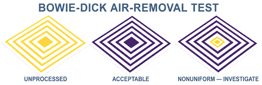
A Bowie-Dick-type test is not:
- A chamber leak-rate test
- A steam-quality test
- A biological sterilization test
- A loaded heat-penetration study
- Proof that every routine load can be sterilized
- Universally applicable to every gravity, liquid, steam-air-mixture, or air-overpressure cycle
The program should distinguish among:
- Chamber leak testing
- Empty-chamber air-removal testing
- Load-specific air-removal or steam-penetration challenges
- Physical temperature mapping
- Biological-indicator challenges
Failure of an air-removal test requires investigation before affected cycles are accepted. Repeating the test until it passes without identifying the cause does not establish control.
Empty-Chamber Heat Distribution
Empty-chamber heat-distribution studies determine whether the sterilizer can establish and maintain the required thermal environment without a load.
The study may evaluate:
- Heating behavior
- Air removal
- Chamber-temperature distribution
- Equilibrium time
- Exposure stability
- Drain response
- Control-sensor agreement
- Monitoring-sensor agreement
- Temperature–pressure relationship
- Exhaust
- Cooling
- Repeatability
Sensor placement should cover the chamber geometry and identified challenge locations, which may include:
- Front, center, and rear
- Upper, middle, and lower elevations
- Near each door
- Near the steam inlet
- Near the drain
- Corners
- Areas affected by shelves or racks
- Locations identified during commissioning or previous studies
The chamber drain is an important monitoring location, but it should not automatically be declared the coldest chamber point. The limiting location must be determined from the study data.
Empty-chamber mapping does not demonstrate heat penetration into packages, vessels, filters, hoses, liquids, or other routine loads. Detailed mapping requirements are addressed in Steam Sterilization Temperature Mapping, Heat Distribution, and Penetration.
Operational Range and Cycle-Type Coverage
OQ should demonstrate that the sterilizer can operate across the range needed by the approved cycle-development and PQ program.
Coverage may include:
- Lowest and highest required exposure temperatures
- Shortest and longest required exposure durations
- Vacuum-pulse ranges
- Gravity-displacement operation
- Porous-load cycles
- Equipment or component cycles
- Liquid cycles
- Air-overpressure cycles
- Cooling ranges
- Drying ranges
- Minimum and maximum control setpoints
- Different chamber accessories or rack arrangements
It is not always necessary to test every combination of parameters. Bracketing may be used when the selected conditions challenge the sterilizer’s required capability and the rationale addresses the functions that change across the range.
A high-temperature empty-chamber run may challenge temperature control but may not challenge heating time, air removal, or low-temperature stability in the same way as another cycle. Bracketing should therefore be function-specific.
Performance Qualification
Performance Qualification demonstrates that approved cycles consistently achieve their intended results with defined loads under routine or justified simulated operating conditions.
PQ should begin only after:
- IQ and required OQ activities are acceptably complete
- Critical deviations are resolved
- Required utilities are available
- Required instruments are calibrated
- Load and cycle development is sufficiently complete
- Load configurations are defined
- Worst-case conditions are identified
- Sampling and BI methods are available
- Acceptance criteria are approved
- Operators are trained
PQ should not be used to discover basic cycle parameters through uncontrolled trial and error. Development may continue during a staged program, but development runs and formal qualification runs must be clearly distinguished.
Load Definition and Worst-Case Selection
Each PQ load should be defined sufficiently to permit reproducible preparation.
The load record should identify:
- Load name and identifier
- Item names
- Item quantities
- Materials
- Dimensions
- Mass or fill volume
- Container and closure
- Packaging or wrapping
- Orientation
- Position
- Rack, cart, shelf, tray, or basket
- Hose or lumen arrangement
- Valve and connection state
- Filter orientation
- Equipment assembly state
- Preconditioning or hold time
- Load temperature before processing
- Photographs or diagrams
- Approved recipe
Worst-case selection should consider:
- Maximum and minimum load
- Greatest thermal mass
- Lowest thermal mass
- Densest packaging
- Most restricted steam pathway
- Longest hose or lumen
- Largest vessel
- Most complex assembly
- Largest liquid fill
- Smallest liquid fill
- Container geometry
- Slowest heating
- Fastest heating and maximum exposure
- Greatest condensate-retention potential
- Most difficult drying condition
- Most severe cooling condition
- Longest permitted pre-cycle hold
- Lowest permitted starting temperature
- Load-position effects
The maximum physical load is not always the worst case for every acceptance criterion. A minimum liquid load may receive the greatest thermal exposure, while a maximum fill may be slowest to heat. One configuration may challenge air removal while another challenges cooling or dryness.
Load-family and bracketing claims should be based on relevant attributes, not only similar item names.
Loaded Heat Distribution and Penetration
Loaded chamber distribution evaluates the thermal environment surrounding the load. Heat penetration evaluates temperature at the actual sterilization targets within the load.
Penetration locations may include:
- Center of a dense porous pack
- Most tightly wrapped item
- Internal equipment surface
- Restricted nozzle or branch
- Valve cavity
- Hose or lumen endpoint
- Filter housing
- Upstream or downstream side of a filter
- Largest liquid fill
- Predicted liquid cold zone
- Most slowly heating container position
- Condensate-retention point
- Shielded or occluded component surface
The study should evaluate:
- Heating profiles
- Exposure-start relationship
- Chamber distribution
- Load equilibration
- Slowest-heating location
- Lowest calculated F₀
- Maximum thermal exposure
- Run-to-run repeatability
- Cooling
- Drying
- Package and component condition
- Agreement with the sterilizer record
Loaded chamber sensors must not be used as substitutes for internal penetration sensors.
The number and placement of sensors should be justified by the chamber, cycle, load geometry, load family, predicted challenge locations, development findings, previous data, and consequences of failing to detect an adverse location.
Microbiological Qualification
Physical measurements and biological indicators provide complementary evidence.
Biological indicators should be selected and used according to the approved sterilization strategy. The program should define:
- Test organism
- BI carrier or configuration
- Population
- Resistance characteristics
- D-value
- z-value where applicable
- Storage conditions
- Expiration
- Certificate review
- Placement
- Retrieval
- Transport
- Incubation
- Positive controls
- Negative controls where applicable
- Growth detection
- Result interpretation
- Handling of damaged or missing indicators
Geobacillus stearothermophilus is commonly used for moist-heat processes because of its resistance characteristics, but organism and BI selection should be justified for the specific process and validation approach.
BI locations should challenge:
- Slowest-heating points
- Lowest-lethality locations
- Restricted steam pathways
- Air-removal challenges
- Internal equipment surfaces
- Hoses and lumens
- Dense or porous packages
- Product-specific challenge locations
A negative BI result does not override unacceptable physical data. A BI may be inactivated at its selected location even when another unmonitored location fails to receive adequate exposure.
A positive BI requires investigation of:
- BI identity and suitability
- Positive-control results
- Placement
- Physical temperature data
- F₀
- Air removal
- Load configuration
- Handling
- Retrieval
- Incubation
- Laboratory controls
- Potential contamination
- Effect on other qualification runs
- Effect on previous conclusions
Additional BI selection, resistance, placement, recovery, and interpretation requirements are addressed in Biological Indicators for Sterilization Validation.
Product, Component, and Package Evaluation
Qualification must evaluate whether the process produces an acceptable load, not only adequate lethality.
Evaluation may include:
- Product appearance
- Assay or potency
- Degradation products
- pH
- Concentration
- Container integrity
- Closure position
- Seal integrity
- Package integrity
- Component functionality
- Filter integrity
- Hose condition
- Material compatibility
- Deformation
- Breakage
- Residual moisture
- Load dryness
- Cooling time
- Safe handling temperature
Maximum thermal exposure can be as important as minimum lethality. A cycle that sterilizes the load but damages the product, closure, filter, package, or equipment assembly is not acceptable.
Product-specific testing may be performed under separate process-validation or stability protocols, but its relationship to sterilizer and cycle release must be defined.
Repeatability and Number of Runs
PQ should demonstrate reproducibility.
The protocol should define:
- Required number of runs
- Whether runs must be consecutive
- Permitted interval between runs
- Whether the load must be rebuilt
- Whether sensors and BIs must be replaced or repositioned
- Required operators
- Required starting conditions
- Acceptance of each run
- Acceptance across the complete series
- Handling of interrupted or failed runs
Three consecutive successful runs are common in sterilization qualification programs, but they should not be presented as a universal number required for every sterilizer, load, and application. The required number should be based on:
- Approved validation strategy
- Applicable regulatory commitments
- Process risk
- Load complexity
- Cycle variability
- Development evidence
- Prior knowledge
- Product and package risk
- Applicable procedures and standards
A failed run cannot be removed from the qualification history and replaced without investigation. Additional passing runs do not cancel an unexplained failure.
Acceptance Criteria
Acceptance criteria should be approved before formal execution and should address the complete study objective.
Equipment and Configuration
Criteria may include:
- Correct sterilizer
- Approved configuration
- Correct software and recipe version
- Correct instruments
- Acceptable calibration status
- Correct load accessories
- Available utilities
- No unauthorized changes
Cycle Execution
Criteria may include:
- Correct recipe
- Complete cycle phases
- Acceptable vacuum performance
- Acceptable leak test
- Acceptable air-removal test where applicable
- Required exposure conditions
- Acceptable pressure behavior
- No unexplained alarms
- Acceptable cycle record
- Acceptable abort and recovery behavior
Physical Performance
Criteria may include:
- Chamber-temperature range
- Sensor-to-sensor spread
- Equilibrium or equilibration time
- Minimum penetration temperature
- Minimum exposure duration
- Minimum F₀
- Maximum F₀ or exposure
- Repeatability
- Cooling requirements
- Dryness
Microbiological Performance
Criteria may include:
- Correct BI population and resistance
- Correct placement
- No growth from exposed indicators
- Acceptable positive controls
- Complete laboratory records
- No unexplained missing or damaged BIs
Load and Product Condition
Criteria may include:
- No unacceptable wetness
- No damaged packaging
- No container breakage
- No closure movement
- Acceptable filter integrity
- Acceptable component function
- Acceptable product-quality results
- Acceptable maximum exposure
No universal chamber-distribution range, equilibration time, minimum F₀, or maximum exposure applies to every sterilizer and load. Criteria must be appropriate for the cycle, load, product, microbiological strategy, development data, and applicable requirements.
Deviations, Invalid Tests, and Repeat Testing
Qualification deviations may include:
- Incorrect system configuration
- Wrong recipe
- Incorrect load
- Incorrect item quantity or orientation
- Failed leak test
- Failed air-removal test
- Cycle alarm
- Incomplete cycle
- Utility interruption
- Sensor failure
- Sensor displacement
- Failed calibration or post-use verification
- Missing data
- Incorrect time synchronization
- Temperature outside limits
- Inadequate F₀
- Excessive exposure
- Positive BI
- Wet load
- Package damage
- Product-quality failure
- Electronic-record failure
- Unauthorized adjustment during execution
The investigation should determine:
- What occurred
- When it occurred
- Which functions, locations, loads, or runs were affected
- Whether the event was caused by the process, equipment, utility, measurement system, laboratory, or execution
- Whether the predefined acceptance criterion was met
- Whether the run remains scientifically interpretable
- Whether other results remain valid
- Whether previous qualification conclusions are affected
- What corrective action is required
- Whether development must be revisited
- Whether repeat testing is required
- What testing must be repeated
A test should not be declared invalid solely because it failed. Invalidity requires documented evidence that the test did not evaluate the intended condition because of an assignable execution or measurement problem.
Repeat testing should be approved and scientifically targeted. It should not be used merely to generate a passing result.
Changes made after a failed test should be evaluated for their effect on previously completed tests. A control adjustment, recipe revision, valve replacement, seal repair, or utility correction may require more than repetition of the visibly failed test.
Requirements Traceability
Traceability demonstrates that qualification addresses the approved requirements and significant risks.
A requirements traceability matrix may link:
| Source | Verification evidence |
|---|---|
| User requirement | Design document, inspection, test, or approved justification |
| Process requirement | Cycle-development study, OQ, PQ, or product evaluation |
| Design feature | DQ, supplier document, IQ, commissioning record, or functional test |
| Identified failure mode | Design control, alarm, interlock, OQ challenge, monitoring, or procedure |
| Critical parameter | Instrument, calibration, control function, cycle record, and PQ evidence |
| Data requirement | Configuration verification, security test, record review, backup, or recovery test |
| Load-family claim | Development evidence, load rationale, heat penetration, and BI placement |
| Release requirement | Approved report, procedure, training, monitoring, and lifecycle control |
Traceability should identify:
- Requirement or risk identifier
- Verification method
- Protocol and test reference
- Result
- Deviation reference
- Final status
- Approval or justification
A requirement should not be marked complete merely because a protocol contains a similar test title. The evidence must demonstrate that the specific requirement was satisfied under applicable conditions.
Qualification Report
The final qualification report should provide a defensible conclusion based on the complete evidence.
The report should include:
- Objective and scope
- System and boundary
- Intended uses
- Sterilizer identification
- Installed configuration
- Software and recipe versions
- Protocols executed
- Commissioning evidence used
- IQ results
- OQ results
- Leak and air-removal results
- Empty-chamber study results
- PQ load configurations
- Heat-distribution and penetration results
- F₀ results
- BI locations and results
- Product, component, and package results
- Run-to-run comparison
- Deviations and investigations
- Changes made during qualification
- Retest rationale and results
- Requirements traceability
- Residual risks
- Open items
- Operating limitations
- Required procedural controls
- Requalification baseline
- Final conclusion
- Approval decision
The report should distinguish:
- Passed tests
- Failed tests
- Invalid tests
- Tests repeated after correction
- Unresolved observations
- Deferred activities
- Conditions of release
Summary tables should not replace raw data. The qualification record should preserve applicable:
- Original electronic mapping files
- Sterilizer cycle records
- Control-system records
- Calibration records
- Sensor and channel assignments
- Load diagrams
- Photographs
- BI records
- Laboratory records
- Calculation files
- Audit-trail evidence
- Deviations
- Approved protocols
- Approved reports
General protocol and reporting controls are addressed in GMP Validation Protocol and Final Report Requirements.
Formal Release
Completion of testing does not automatically authorize GMP use.
Release should confirm that:
- Required lifecycle activities are complete
- Acceptance criteria have been met
- Deviations are resolved or acceptably controlled
- Requirements traceability is complete
- Residual risks are acceptable
- Approved recipes are identified
- Approved load configurations are identified
- Operating ranges and limitations are documented
- Routine cycle-review requirements are defined
- Required procedures are approved
- Operators and reviewers are trained
- Calibration and maintenance requirements are active
- BI and chemical-indicator requirements are defined
- Leak-test and air-removal-test requirements are defined
- Data backup and retention controls are active
- Requalification requirements are established
- Quality approval has been obtained
Release should distinguish among:
- Release of the physical sterilizer
- Release of a control-system configuration
- Release of an individual recipe
- Release of a load configuration
- Release of a load family
- Release of a product sterilization process
A qualified sterilizer is not automatically approved for every load that physically fits inside the chamber.
Conditional release should be used only when remaining items do not compromise sterility assurance, product quality, data integrity, safety, or the ability to operate within the qualified state. Conditions, responsibilities, due dates, and restrictions must be documented.
Transfer to Routine Control
Qualification conclusions should be transferred into routine operating controls.
These may include:
- Approved load diagrams
- Load-family boundaries
- Minimum and maximum quantities
- Required item orientation
- Packaging requirements
- Approved recipe numbers and versions
- Critical parameter limits
- Cycle-acceptance requirements
- Alarm and abort rules
- Leak-test frequency
- Air-removal-test frequency where applicable
- BI and chemical-indicator requirements
- Routine cycle-record review
- Product- or load-release requirements
- Calibration requirements
- Preventive-maintenance tasks
- Sterile-air-filter controls
- Requalification sensor and BI locations
- Change-control requirements
- Periodic-review inputs
Qualification has not been effectively transferred when the validation report identifies a critical load arrangement or limiting location but routine procedures permit uncontrolled variation.
Regulatory and Standards Context
For US drug manufacturing, 21 CFR 211.113(b) requires written procedures that include validation of sterilization processes used for drug products purporting to be sterile.
21 CFR 211.63 requires equipment to be appropriately designed, adequately sized, and suitably located for its intended use, cleaning, and maintenance.
21 CFR 211.68 establishes controls for automatic, mechanical, and electronic equipment. Its applicability should be evaluated for sterilizer controls, calculations, electronic records, and system checks.
21 CFR 211.100 addresses written procedures and the recording and justification of deviations.
FDA’s Submission Documentation for Sterilization Process Validation addresses sterilization-process information supporting human and veterinary drug applications.
Relevant USP chapters include:
- USP
<1211>Sterility Assurance - USP
<1229>Sterilization of Compendial Articles - USP
<1229.1>Steam Sterilization by Direct Contact - USP
<1229.2>Moist Heat Sterilization of Aqueous Liquids - USP
<1229.5>Biological Indicators for Sterilization - USP
<1229.9>Physicochemical Integrators and Indicators for Sterilization
Cite the USP chapter numbers without adding paywalled USP links.
ISO 17665:2024 specifies requirements for development, validation, and routine control of moist-heat sterilization processes for medical devices. FDA currently lists the 2024 edition as a recognized consensus standard for medical devices.
The formal scope of ISO 17665 is medical devices. Its technical principles may support pharmaceutical applications after documented applicability assessment, but the standard should not be represented as a pharmaceutical-drug regulation.
EN 285 and PDA Technical Report No. 1 may provide useful technical guidance for particular equipment and applications. Their applicability should be defined rather than assumed.
The authority and scope of the applicable regulations and standards are addressed in Sterilization Regulations, Standards, and Validation Lifecycle.
Common Qualification Errors
Frequent errors include:
- Beginning qualification without approved intended use or requirements
- Treating vendor specifications as the site URS
- Treating FAT completion as Design Qualification
- Repeating commissioning tests without evaluating whether the original evidence can be used
- Using commissioning evidence that lacks actual results or configuration traceability
- Starting qualification while equipment remains under uncontrolled adjustment
- Treating IQ as a document-collection exercise without field verification
- Failing to establish the software, firmware, recipe, and instrument baseline
- Calibrating instruments outside the range used for qualification
- Failing to distinguish control and monitoring sensors
- Testing only normal automatic operation
- Failing to challenge alarms, interlocks, failures, and recovery
- Treating a chamber leak test as proof of air removal
- Treating a Bowie-Dick test as proof of sterilization
- Applying Bowie-Dick testing to cycle types for which it is not technically applicable
- Treating empty-chamber mapping as proof of loaded heat penetration
- Assuming the chamber drain is always the coldest location
- Qualifying only the maximum load
- Failing to evaluate minimum loads and maximum thermal exposure
- Defining load families based only on similar item names
- Using chamber-space sensors instead of internal penetration sensors
- Placing BIs without relation to physical mapping or load-development evidence
- Using negative BIs to override unacceptable physical results
- Applying one universal F₀ requirement to every load without a microbiological and product basis
- Failing to evaluate product, closure, package, filter, or component effects
- Declaring a failed test invalid without evidence
- Repeating a failed run without investigation
- Counting additional passing runs as cancellation of a previous failure
- Making configuration or recipe changes without assessing previously completed tests
- Closing traceability based only on protocol titles
- Releasing the sterilizer without identifying approved recipes and loads
- Assuming that a qualified sterilizer is suitable for every load that fits inside it
- Failing to transfer load configuration and acceptance requirements into routine procedures
- Failing to establish requalification triggers from the initial qualification evidence
Conclusion
Steam sterilizer qualification must connect equipment capability with the developed sterilization process.
IQ establishes the controlled installed baseline. OQ demonstrates that the sterilizer, controls, alarms, interlocks, records, chamber-integrity functions, air-removal functions, and thermal performance operate throughout their required ranges. PQ demonstrates that defined loads consistently receive adequate heat penetration and microbiological lethality without unacceptable product, component, container, closure, or package effects.
A defensible qualification program begins with intended use, requirements, design review, risk assessment, and controlled commissioning evidence. It uses justified physical and microbiological challenges, investigates failures, maintains requirements traceability, and ends with a formal release decision that identifies the approved equipment configuration, recipes, loads, operating limits, and lifecycle controls.
Qualification establishes what the sterilizer is approved to do. Routine monitoring, maintenance, calibration, change control, periodic review, and requalification provide the continuing evidence that it remains capable of doing it