

Dry Heat Sterilization Qualification and Lifecycle Control
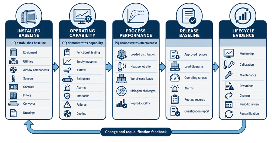
Dry heat sterilization qualification demonstrates that an oven or continuous tunnel is installed correctly, operates as intended, and repeatedly delivers the required microbial lethality to the most difficult-to-heat locations within approved load configurations.
Qualification must evaluate more than chamber or zone temperature. The evidence should establish control of:
- Heating and exposure
- Air circulation and temperature distribution
- Heat penetration into load items
- Cycle timing
- Conveyor speed for continuous tunnels
- Cooling conditions
- Alarms, interlocks, and failure responses
- Sterile-boundary protection where applicable
- Biological effectiveness
- Routine monitoring and record review
- Changes, maintenance, and requalification
Dry heat sterilization and dry heat depyrogenation may use similar equipment, but their validation claims remain different. Sterilization demonstrates microbial inactivation. Depyrogenation demonstrates endotoxin reduction. Qualification protocols must identify which claim or claims apply.
Purpose and Scope
This article covers the qualification and lifecycle control of:
- Static-air batch ovens
- Forced-air circulation ovens
- Pass-through dry heat ovens
- Continuous dry heat tunnels
- Associated heating, airflow, conveyor, cooling, control, and monitoring systems
The article addresses:
- Qualification planning and prerequisites
- Installation qualification
- Operational qualification
- Performance qualification
- Airflow studies
- Empty-chamber and empty-zone mapping
- Loaded heat-distribution studies
- Heat-penetration studies
- Biological-indicator challenges
- Conveyor and belt-speed verification
- Alarm and failure testing
- Cooling-zone control
- Acceptance and release
- Routine cycle monitoring
- Maintenance and calibration
- Change control
- Periodic review
- Requalification
Dry heat process principles, equipment types, cycle development, load compatibility, and operating parameters are addressed in Dry Heat Sterilization Systems and Process Principles.
Detailed endotoxin-challenge qualification belongs in Depyrogenation Validation and Qualification.
Qualification Lifecycle Position
Qualification should confirm an already defined process rather than serve as uncontrolled cycle development.
Before formal execution, the following should be available:
- Approved intended use
- Defined sterilization objective
- Approved equipment and process requirements
- Completed design review
- Defined equipment boundary
- Approved cycle or tunnel operating strategy
- Defined load families
- Approved load configurations
- Identified critical operating parameters
- Material-compatibility evidence
- Preliminary heat-transfer information
- Proposed worst-case conditions
- Acceptance criteria
- Calibration strategy
- Biological-challenge rationale
- Deviations and change-control procedures
- Approved qualification protocols
Unresolved design or development issues should not be transferred into OQ or PQ without a documented plan and acceptance rationale.
The broader requirements-to-retirement structure is addressed in GMP Validation Life Cycle: Requirements to Retirement.
Qualification Strategy
The qualification strategy should be based on:
- Equipment type
- Intended sterilization use
- Load characteristics
- Required microbial lethality
- Process criticality
- Operating range
- Equipment complexity
- Control-system architecture
- Sterile-boundary requirements
- Existing commissioning evidence
- Supplier documentation
- Previous qualification history
- Relationship to an aseptic filling line
- Whether depyrogenation is also claimed
Supplier or commissioning records may support qualification when their scope, methods, data integrity, calibration status, acceptance criteria, and execution controls are documented and accepted. Their availability does not automatically make repeat testing unnecessary.
The strategy should identify which evidence will be:
- Accepted from the supplier
- Leveraged from commissioning
- Verified during IQ
- Challenged during OQ
- Demonstrated under loaded conditions during PQ
- Repeated during requalification
- Monitored during routine operation
Equipment and Process Boundaries
The qualification boundary should identify all systems that can affect the sterilization result or sterile state.
For a batch oven, the boundary may include:
- Chamber and insulation
- Doors, seals, and latches
- Shelves, racks, and carts
- Heating elements
- Circulation fans
- Supply and return paths
- Air filters
- Cooling system
- Temperature sensors
- Independent monitoring sensors
- Controller or PLC
- Recipe-management functions
- Cycle timer
- Alarm system
- Data recorder or historian
- Power supply
- Exhaust system
- Pass-through interlocks
- Adjacent controlled areas
For a continuous tunnel, the boundary may also include:
- Container infeed
- Conveyor or transport belt
- Belt drive
- Speed encoder or transmitter
- Preheating zone
- High-temperature treatment zone
- Cooling zone
- Zone separation
- HEPA-filtered air systems
- Zone-pressure controls
- Container tracking
- Reject or diversion functions
- Tunnel-to-washer interface
- Tunnel-to-filler interface
- Filling-line permissives
- Line-stop and restart logic
Interfaces should be assigned to identified system owners. A function should not be omitted merely because its hardware belongs to another equipment package.
Installation Qualification
Installation qualification establishes the documented installed baseline.
Equipment Identification
IQ should verify:
- Manufacturer
- Model
- Serial number
- Equipment identification number
- Chamber or tunnel dimensions
- Rated temperature range
- Rated load or throughput
- Heating capacity
- Airflow-system configuration
- Conveyor configuration
- Installed location
- Equipment orientation
- Pass-through direction
- Connected upstream and downstream equipment
Drawings and Technical Documentation
Applicable documents may include:
- General arrangement drawings
- Mechanical drawings
- Electrical drawings
- Airflow schematics
- Duct and filter drawings
- Instrument lists
- Sensor-location drawings
- Wiring diagrams
- Control-panel drawings
- Input/output lists
- Alarm lists
- Software and firmware records
- Conveyor drawings
- Utility requirements
- Spare-parts lists
- Operation and maintenance manuals
- Material certificates
- Filter certificates
Documents should reflect the installed condition or have controlled discrepancies assigned for correction.
Materials of Construction
IQ should verify materials for:
- Chamber surfaces
- Shelves and racks
- Conveyor or belt
- Container-contact guides
- Door seals and gaskets
- Insulation containment
- Internal fasteners
- Air ducts
- Filter housings
- Cooling-zone surfaces
Material verification should focus on cleanability, heat resistance, corrosion resistance, particulate generation, and compatibility with the intended process.
Utilities
Applicable utilities may include:
- Electrical power
- Instrument air
- Cooling water
- Chilled water
- Compressed air
- HVAC connections
- Exhaust
- Network services
- Time-synchronization service
- Emergency power
IQ should verify utility identity, capacity, connection, isolation, labeling, and conformity with approved requirements.
Heating and Air-Circulation Components
Installation checks should address:
- Heating-element quantity and location
- Heater ratings
- Fan identification
- Fan rotation
- Fan-motor ratings
- Belt or direct-drive arrangement
- Supply and return openings
- Dampers
- Airflow restrictions
- Filter type and location
- Filter-housing installation
- Access for inspection and maintenance
Fan rotation may be functionally confirmed during OQ, but the installed fan, motor, and wiring baseline belongs in IQ.
Doors and Access Panels
IQ should verify:
- Door construction
- Seal materials
- Hinge and latch installation
- Door-switch installation
- Pass-through interlock arrangement
- Observation windows
- Access-panel fasteners
- Surface condition
- Door-adjustment capability
- Protection against opening during hazardous conditions
Instrumentation
The qualification record should identify:
- Control sensors
- Independent monitoring sensors
- Overtemperature sensors
- Airflow or pressure sensors
- Fan-status devices
- Conveyor-speed instruments
- Door-position switches
- Timers
- Data-recording channels
- Cooling-zone sensors
- Filter differential-pressure instruments
For each critical instrument, IQ should verify:
- Identification
- Manufacturer and model
- Range
- Accuracy
- Resolution
- Installed location
- Calibration status
- Calibration traceability
- Connection to the correct control or monitoring channel
Control System
IQ should establish the installed configuration of:
- PLC or controller
- Human-machine interface
- Software or firmware version
- Input/output assignments
- Recipe database
- Alarm database
- User roles
- Audit-trail capability where applicable
- Data storage
- Backup and restoration functions
- Interfaces
- Time synchronization
- Report configuration
- Electronic-record retention
Software functions are tested during OQ, but the approved configuration baseline should be established during IQ.
HEPA Filters
Where HEPA-filtered air protects sterile or depyrogenated items, IQ should verify:
- Filter identification
- Grade or efficiency
- Location
- Orientation
- Housing
- Seal arrangement
- Installation records
- Access for integrity testing
- Replacement requirements
- Operating-temperature suitability
FDA specifically identifies HEPA filters installed in dry heat depyrogenation tunnels and ovens as filters requiring leak-testing consideration. Where conventional hot-zone testing is not feasible, an alternate method should be technically justified and documented.
Operational Qualification
Operational qualification demonstrates that the installed system functions throughout its approved operating range. OQ should evaluate:
- Startup
- Heating
- Temperature control
- Air circulation
- Exposure timing
- Cooling
- Door and access control
- Conveyor operation
- Recipe execution
- Data recording
- Alarms
- Interlocks
- Failure responses
- Shutdown
- Restart
- Manual operation where permitted
- Recovery from interruptions
Testing should challenge functions that can affect lethality, load quality, record completeness, or sterile-boundary control.
Instrument Calibration and Qualification Sensors
The control and monitoring sensors used by the equipment must be distinguished from the independent sensors used during qualification.
Qualification sensors should have:
- Appropriate range
- Suitable accuracy
- Adequate resolution
- Documented identification
- Traceable calibration
- Defined measurement uncertainty
- Suitable response time
- Protection against movement
- Compatibility with the study temperature
Qualification sensors should normally be calibrated before and after the study campaign. A failed post-use calibration requires assessment of all affected data.
The protocol should define:
- Permitted pre-use and post-use error
- Sensor-handling requirements
- Data-acquisition interval
- Channel identification
- Treatment of missing data
- Treatment of shifted or damaged sensors
- Synchronization with the equipment record
- Calculation and rounding rules
The qualification measurement system should be sufficiently accurate to evaluate the approved acceptance limits. A mapping system with uncertainty too large relative to the permitted temperature range cannot provide conclusive evidence.
Airflow Qualification
Airflow affects heating rate, spatial uniformity, heat penetration, cooling, and protection of processed items.
Batch Oven Airflow
Batch-oven airflow studies should assess, as applicable:
- Fan direction
- Fan speed or operating status
- Supply-air paths
- Return-air paths
- Shelf and rack effects
- Door-area circulation
- Corner and wall conditions
- Potential stagnant regions
- Airflow obstruction
- Filter differential pressure
- Response to fan failure
- Recovery after interruption
Airflow characterization may use:
- Engineering airflow measurements
- Velocity profiles
- Differential-pressure measurements
- Temperature-response studies
- Airflow visualization performed under justified conditions
- Fan-performance records
- Computational analysis supported by field verification
A room-temperature airflow visualization does not independently establish airflow behavior at sterilization temperature. Differences in air density, buoyancy, equipment expansion, and fan performance should be considered when interpreting results.
Tunnel Airflow
Tunnel airflow qualification should evaluate:
- Flow within each zone
- Flow between zones
- Pressure relationships
- Heating-zone balance
- Hot-zone balance
- Cooling-zone airflow
- Air movement at zone transitions
- Tunnel infeed conditions
- Tunnel discharge conditions
- Interface with the filling line
- Effects of conveyor openings
- Effects of line stoppage
- Effects of filter loading
- Fan or airflow failure
Where cooled sterile containers discharge directly into an aseptic filling environment, qualification should demonstrate that airflow does not permit contamination to move toward the processed containers or critical filling zone.
Airflow studies should be coordinated with:
- HEPA integrity testing
- Filter differential-pressure testing
- Nonviable particle qualification where applicable
- Pressure-alarm testing
- Filling-line airflow studies
- Intervention and line-stoppage assessment
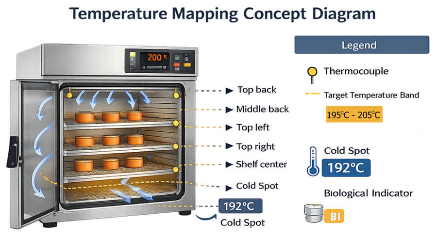
Empty-Chamber Temperature Mapping
Empty-chamber mapping evaluates the oven without production load obstruction. Its purposes include:
- Characterizing spatial temperature distribution
- Identifying persistent hot and cold areas
- Evaluating control stability
- Comparing chamber sensors with independent measurements
- Assessing heat-up and equilibration
- Supporting loaded-study sensor placement
- Detecting installation or airflow deficiencies
Sensor placement should consider:
- Chamber corners
- Center
- Door-adjacent locations
- Supply-air region
- Return-air region
- Upper and lower elevations
- Each shelf level
- Control-sensor vicinity
- Monitoring-sensor vicinity
- Areas shielded from direct airflow
- Locations identified by airflow studies
There is no universal number of mapping sensors appropriate for every oven. Sensor quantity and placement should reflect:
- Chamber size
- Geometry
- Shelf arrangement
- Airflow design
- Prior mapping information
- Required spatial resolution
- Expected gradients
- Measurement-system capability
The protocol should prevent convenient symmetrical placement from replacing risk-based coverage.
Empty-Mapping Conditions
Mapping may need to challenge:
- Minimum approved setpoint
- Maximum approved setpoint
- Typical production setpoint
- Minimum operating duration
- Extended operating duration
- Different shelf configurations
- Minimum and maximum fan settings
- Heating from a defined cold start
- Restart after interruption
The selected conditions should demonstrate the operating range actually claimed. Testing only the nominal setpoint does not establish capability at qualified lower and upper limits.
Empty-Mapping Evaluation
Evaluation should include:
- Time to reach setpoint
- Time to reach the defined equilibration condition
- Minimum recorded temperature
- Maximum recorded temperature
- Spatial temperature range
- Temporal variation during exposure
- Control-sensor agreement
- Monitoring-sensor agreement
- Reproducibility
- Recurring cold or hot locations
- Sensor anomalies
- Data completeness
The exposure period should begin according to the approved cycle logic. It should not be retroactively selected from the most favorable part of the temperature record.
Tunnel Temperature and Zone Mapping
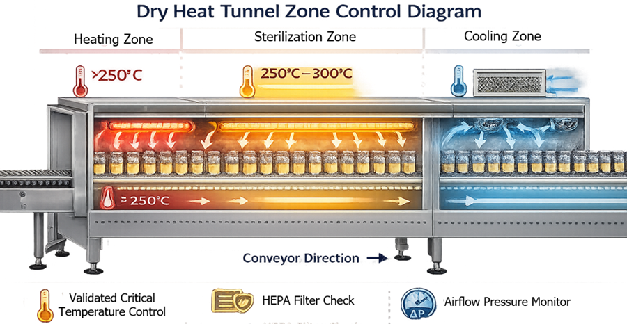
Tunnel mapping must evaluate the complete container path, not only the nominal hot-zone setpoint.
Qualification should establish:
- Temperature profile through the preheating zone
- Entry into the high-temperature zone
- Residence within the qualified treatment region
- Exit from the treatment region
- Cooling-zone performance
- Container discharge temperature
- Effects of container position across belt width
- Effects of container density and spacing
- Effects of line speed
- Effects of zone transitions
- Reproducibility
Traveling sensors or instrumented containers may be used to characterize actual container exposure. Their mass, geometry, response time, mounting method, and effect on normal container movement should be justified.
Fixed tunnel sensors remain important for control and routine monitoring, but they do not independently establish the thermal history of containers moving through the system.
Conveyor and Belt-Speed Verification
Conveyor speed directly affects residence time. Tunnel qualification should verify:
- Displayed speed
- Actual speed
- Speed range
- Speed stability
- Encoder or transmitter accuracy
- Belt slip
- Speed under representative load
- Speed across startup and steady-state operation
- Response to overspeed
- Response to underspeed
- Response to stoppage
- Recovery after restart
- Container tracking through affected zones
Verification should use an independent calibrated method appropriate to the design. The relationship among belt speed, treatment-zone length, and exposure time should be documented.
The qualification should challenge the fastest approved belt speed because it normally produces the shortest treatment-zone residence time. A slower speed may represent the maximum thermal-exposure condition and should be evaluated for container compatibility and excessive heating.
FDA’s aseptic-processing guidance specifically identifies instruments used to measure dry heat tunnel belt speed as devices requiring routine calibration.
Alarm, Interlock, and Failure Testing
OQ should challenge significant abnormal conditions rather than only confirm that alarm text appears.
Applicable challenges may include:
- Low chamber temperature
- High chamber temperature
- Zone-temperature deviation
- Control-sensor failure
- Monitoring-sensor failure
- Sensor disagreement
- Heater failure
- Fan failure
- Airflow interruption
- Filter differential-pressure excursion
- Door-open condition
- Door-interlock failure
- Conveyor overspeed
- Conveyor underspeed
- Conveyor stoppage
- Cooling-system failure
- Cooling-zone temperature excursion
- Pressure or airflow-boundary failure
- Data-recording interruption
- Network interruption
- Power loss
- Emergency stop
- Incorrect recipe selection
- Unauthorized parameter change
- Filling-line stoppage
- Upstream washer interruption
- Downstream equipment unavailability
For each challenge, testing should verify:
- Detection
- Alarm generation
- Alarm message
- Time delay
- Audible or visual indication
- Equipment response
- Heater response
- Conveyor response
- Door response
- Data recording
- Event timestamp
- Operator acknowledgement
- Remote notification where applicable
- Recovery requirements
- Restart restrictions
- Identification of affected product or containers
A successful alarm challenge requires evidence that the complete protective action occurred. Confirmation that an alarm banner appeared is insufficient when the intended control includes automatic shutdown, conveyor stop, batch abort, or product segregation.
Power-Failure and Restart Testing
Power-failure testing should evaluate:
- Safe equipment state
- Heater de-energization
- Fan behavior
- Conveyor behavior
- Door locking or release
- Data retention
- Clock and timestamp behavior
- Alarm retention
- Recipe retention
- Container location tracking
- Recovery of the monitoring record
- Restrictions on cycle continuation
- Restart logic
- Identification of affected load or container interval
For continuous tunnels, loss of container position or exposure history may prevent reliable separation of acceptable and potentially affected containers. The rejection boundary should expand when traceability is inadequate.
Cooling-Zone Qualification
Cooling is part of the validated process when sterile or depyrogenated items must remain protected before aseptic filling or controlled unloading.
Qualification should address:
- Cooling capacity
- Discharge-temperature range
- Cooling time
- Air temperature
- Airflow
- HEPA filter integrity
- Filter differential pressure
- Pressure relationships
- Nonviable particle control where applicable
- Zone recovery
- Container density
- Belt speed
- Line stoppage
- Filling-line interruption
- Maximum container residence
- Container breakage
- Condensation risk
- Sterile-boundary protection
A cooling-zone temperature study should confirm that containers are sufficiently cool for downstream handling without creating a condition that compromises container quality or aseptic operations.
The cooling-zone airflow study should address the tunnel discharge and its interface with the filling line. Qualification of the tunnel and filling environment should provide compatible conclusions rather than treating the interface as outside both systems.
Performance Qualification
PQ demonstrates that the approved process repeatedly achieves its sterilization objective under representative and worst-case loaded conditions.
PQ should normally include:
- Approved production load or container family
- Defined load diagrams
- Loaded heat-distribution studies
- Heat-penetration studies
- Biological challenges
- Minimum exposure conditions
- Maximum exposure assessment
- Worst-case item or location
- Approved operating parameters
- Repeated successful runs
- Routine operating personnel and procedures
- Production-representative equipment configuration
- Complete cycle records
- Predefined acceptance criteria
The number of runs should be justified based on process variability, equipment history, load complexity, prior development, and applicable procedures. Three runs are common, but repetition should not be treated as a substitute for technically representative challenges.
Load Families and Worst-Case Selection
A load family may group items that can be supported by the same qualified cycle. The grouping rationale should consider:
- Material
- Mass
- Geometry
- Wall thickness
- Thermal conductivity
- Packaging
- Wrapping
- Container type
- Fill depth
- Internal cavities
- Airflow obstruction
- Shelf or rack location
- Load density
- Heat-penetration behavior
- Required lethality
- Maximum acceptable thermal exposure
The worst case depends on the property being challenged.
Potential minimum-lethality worst cases include:
- Greatest mass
- Deepest powder bed
- Densest loading
- Most insulated item
- Most restricted airflow
- Lowest initial temperature
- Lowest approved setpoint
- Shortest approved exposure time
- Fastest approved belt speed
- Most difficult belt position
Potential maximum-exposure worst cases include:
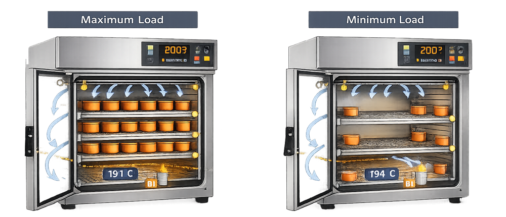
- Minimum load
- Smallest item
- Lowest mass
- Slowest approved belt speed
- Highest approved setpoint
- Extended process interruption
- Position with greatest radiant exposure
One load configuration may not challenge both insufficient exposure and excessive exposure.
Loaded Heat-Distribution Studies
Loaded heat-distribution studies measure conditions throughout the chamber or tunnel while the approved load is present.
Their purposes include:
- Demonstrating temperature distribution around the load
- Evaluating the effect of airflow obstruction
- Confirming chamber or zone control
- Identifying loaded cold and hot areas
- Supporting heat-penetration locations
- Comparing different load configurations
- Demonstrating reproducibility
Distribution sensors should be positioned in the chamber or load space. They should not all be attached to or inserted into load items, because that would convert the study into a penetration assessment.
Loaded distribution may differ materially from empty mapping. A location that was acceptable during empty mapping may become a cold region when a tray, rack, powder container, or dense component group changes the airflow pattern.
Heat-Penetration Studies
Heat-penetration studies measure temperature at or within the part of the load expected to be most difficult to heat.
Potential penetration locations include:
- Interior of a wrapped assembly
- Center of a dense component group
- Internal cavity
- Deepest powder location
- Center of an oil container
- Interface between nested components
- Shielded surface
- Thickest material section
- Container location with the shortest tunnel exposure
- Location identified by development or prior failures
Penetration sensors should be secured so their sensing points remain at the intended locations throughout the study.
The protocol should distinguish:
- Chamber or zone temperature
- Load-space distribution temperature
- Item-surface temperature
- Internal penetration temperature
- Equipment control temperature
These temperatures answer different questions and should not be treated as interchangeable.
FDA recommends carefully designed heat-distribution and heat-penetration studies for dry heat sterilization, particularly for powders because of their insulating effects.
Biological-Indicator Challenges
Biological indicators provide direct microbial evidence of process effectiveness when appropriately selected, characterized, placed, exposed, recovered, and interpreted.
The biological-indicator strategy should define:
- Test organism
- Carrier or substrate
- Population
- D-value
- Resistance characteristics
- Lot identification
- Storage conditions
- Expiration
- Positive controls
- Negative controls where applicable
- Placement locations
- Recovery method
- Incubation conditions
- Acceptance criteria
- Relationship to the required lethality or SAL
Bacillus atrophaeus spores are commonly used for dry heat sterilization, but organism selection and resistance must be justified for the actual process.
The carrier can affect resistance. A BI qualified on one carrier should not automatically be treated as equivalent when inoculated onto another material or placed into a different product matrix.
Biological indicators should be placed:
- At identified cold locations
- At difficult-to-heat load locations
- Within or adjacent to representative items
- Near penetration sensors where practical
- Across different shelves or belt positions
- At locations supported by thermal-development data
Placement near the penetration sensor helps correlate predicted thermal lethality with observed microbial inactivation.
The BI strategy should not compensate for inadequate physical measurements. Conversely, a satisfactory temperature profile does not eliminate the need for applicable microbial evidence.
Detailed BI selection and control are addressed in Biological Indicators for Sterilization Validation.
Boundary With Depyrogenation Challenges
When the process claims depyrogenation, endotoxin-challenge studies must establish the applicable endotoxin-reduction objective.
FDA states that dry heat depyrogenation validation data should generally demonstrate at least a 99.9 percent, or 3-log, endotoxin reduction. FDA also states that when this level of dry heat depyrogenation has been successfully validated using an endotoxin challenge, a separate BI sterilization challenge would not be indicated for that validated process.
This conclusion should not be generalized to:
- Lower-temperature sterilization cycles
- Processes without a validated endotoxin challenge
- Different loads or containers
- Operating conditions outside the validated range
- Equipment used only for sterilization
Detailed endotoxin-challenge requirements belong in Depyrogenation Validation and Qualification.
PQ Reproducibility
PQ runs should demonstrate that:
- The same approved recipe was used
- Load configuration was reproducible
- Equipment starting conditions were controlled
- Critical parameters remained within limits
- Distribution remained acceptable
- Penetration locations achieved the required exposure
- Biological acceptance criteria were met
- Cooling remained acceptable
- Alarms and interruptions were properly evaluated
- Data records were complete
- Results were consistent across runs
Repeatability should be evaluated quantitatively where appropriate. A study should not be accepted merely because every result remained narrowly above a minimum criterion if the results show unexplained deterioration or large run-to-run variation.
Acceptance Criteria
Acceptance criteria should be approved before execution and traceable to the intended sterilization objective.
Applicable criteria may address:
- Equipment installation
- Instrument calibration
- Setpoint accuracy
- Control stability
- Heat-up time
- Equilibration
- Minimum exposure temperature
- Maximum exposure temperature
- Exposure duration
- Spatial temperature range
- Temporal variation
- Accumulated lethality
- Airflow condition
- Fan status
- Conveyor speed
- Residence time
- Cooling-zone temperature
- Discharge temperature
- Filter integrity
- Pressure relationships
- Alarm response
- Failure response
- Data completeness
- BI inactivation
- Positive-control recovery
- Reproducibility
Acceptance criteria should identify the calculation method, time boundaries, sensor treatment, rounding convention, and handling of anomalous measurements.
A general statement such as “temperature distribution was uniform” is not an adequate criterion unless uniformity is numerically defined.
Qualification Deviations and Failed Studies
A failed or anomalous qualification run should be investigated before repetition.
The investigation should determine whether the result reflects:
- Equipment failure
- Process inadequacy
- Load-design problem
- Sensor failure
- Incorrect sensor placement
- Data-acquisition failure
- Calibration problem
- Operator error
- Protocol ambiguity
- BI handling or laboratory error
- Uncontrolled environmental condition
- Unapproved equipment change
A repeat run should not erase the original failure. The record should preserve:
- Original data
- Investigation
- Root-cause assessment
- Product or process impact
- Corrective action
- Retest rationale
- Retest scope
- Final conclusion
If the failure reveals inadequate cycle development or equipment design, additional qualification repetition alone is not a corrective action.
Qualification Report and Release
The final report should summarize:
- Approved scope
- Equipment boundary
- Protocols executed
- Deviations
- Changes during execution
- IQ results
- OQ results
- Mapping results
- Airflow results
- Conveyor results
- Cooling-zone results
- PQ results
- Biological results
- Statistical or trend evaluation
- Residual risks
- Open items
- Operating restrictions
- Approved load families
- Approved load diagrams
- Approved recipes
- Routine monitoring requirements
- Requalification requirements
- Release decision
Release should establish the baseline against which routine cycles, maintenance, changes, and future studies will be evaluated.
Routine Monitoring and Cycle Review
Routine monitoring should verify continued operation within the qualified range.
For batch ovens, cycle records may include:
- Equipment identification
- Recipe
- Load identity
- Load configuration
- Chamber temperature
- Independent monitoring temperature
- Exposure-start time
- Exposure duration
- Fan status
- Door status
- Cooling endpoint
- Alarms
- Interruptions
- Operator actions
- Cycle acceptance
For tunnels, records may include:
- Zone temperatures
- Conveyor speed
- Fan status
- Airflow or pressure conditions
- Filter differential pressure
- Cooling-zone temperature
- Line speed
- Container configuration
- Container density
- Start and stop times
- Tunnel stoppages
- Filling-line interruptions
- Rejected-container interval
- Alarms and acknowledgements
Routine review should verify the actual process record. Automatic “cycle complete” or “batch accepted” status should not replace evaluation of critical parameters, alarms, interruptions, configuration, and data completeness.
Calibration and Maintenance
Lifecycle control should include:
- Calibration of temperature sensors
- Calibration of qualification instruments
- Timer verification
- Conveyor-speed calibration
- Airflow and pressure-instrument calibration
- Filter differential-pressure calibration
- Door-switch verification
- Alarm testing
- Fan inspection
- Heater inspection
- Conveyor inspection
- Belt-tension or slip assessment
- Door-seal inspection
- Filter inspection and replacement
- Data-system maintenance
- Backup and restoration verification
The calibration and maintenance program is addressed in GMP Calibration Program and Metrology Control.
Post-maintenance testing should reflect the function affected. Heater replacement may require temperature-distribution assessment. Fan work may require airflow and mapping studies. Conveyor work may require belt-speed and residence-time verification.
Change Control
Changes should be assessed for their effect on:
- Heat delivery
- Temperature distribution
- Heat penetration
- Exposure timing
- Airflow
- Cooling
- Load compatibility
- Microbial lethality
- Sterile-boundary control
- Data integrity
- Approved recipes
- Routine monitoring
- Previous qualification conclusions
Relevant changes may include:
- Heater replacement
- Fan replacement
- Fan-speed change
- Airflow modification
- Damper adjustment
- Filter replacement
- Filter-housing work
- Sensor replacement
- Sensor relocation
- Controller replacement
- PLC or software change
- Recipe change
- Alarm-limit change
- Conveyor repair
- Encoder replacement
- Belt replacement
- Belt-speed range change
- Chamber modification
- Tunnel-zone modification
- Cooling-system modification
- Door or seal replacement
- Load change
- Packaging change
- Container-size change
- Throughput change
- Washer or filler interface change
- Equipment relocation
- Extended shutdown
The change assessment should identify the affected requirement, function, evidence, operating procedure, and qualification study.
Change-impact principles are addressed in GMP Change Control and Validation Impact Assessment.
Periodic Review
Periodic review should evaluate whether the approved qualification baseline remains defensible.
Review inputs may include:
- Routine cycle records
- Temperature trends
- Conveyor-speed trends
- Cooling-zone trends
- Alarm history
- Deviations
- Failed or aborted cycles
- Maintenance history
- Calibration history
- Sensor drift
- Filter-integrity results
- Environmental or particle data where applicable
- BI or endotoxin verification data
- Product or load changes
- Recipe changes
- Software changes
- Repeated operator interventions
- Vendor support status
- Obsolescence
- Previous requalification results
- Open CAPAs
Potential conclusions include:
- Qualified state remains supported
- Targeted verification is required
- Partial requalification is required
- Comprehensive requalification is required
- Continued use requires restrictions
- Equipment should be removed from service
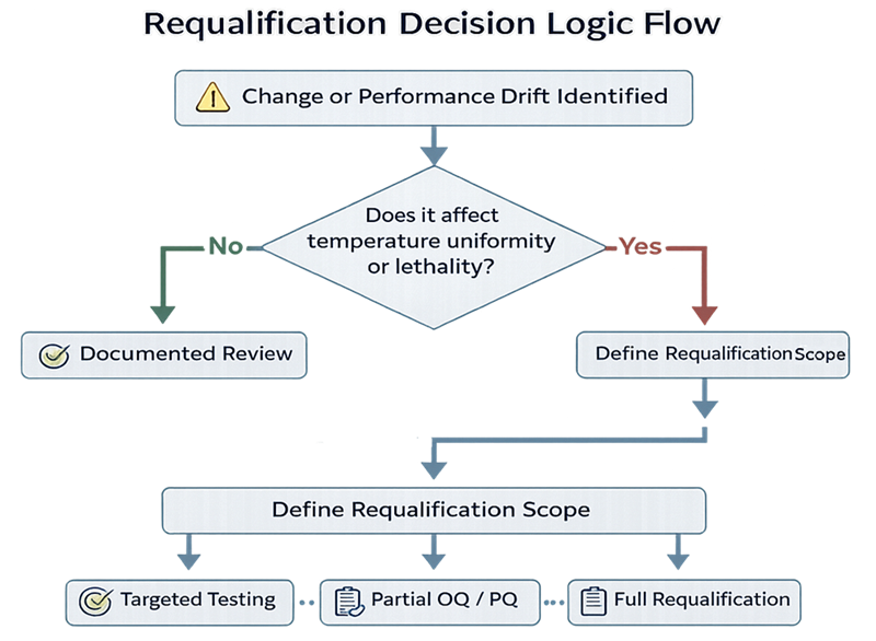
Requalification
Requalification may be scheduled, event-driven, or both.
Potential triggers include:
- Defined requalification interval
- Adverse performance trend
- Repeated temperature excursion
- Unexplained BI failure
- Failed endotoxin challenge
- Major maintenance
- Heating-system modification
- Airflow-system modification
- Filter or housing work
- Sensor relocation
- Control-system change
- Conveyor or speed-control change
- Cooling-zone modification
- Load-family change
- Container change
- Extended shutdown
- Relocation
- Sterile-boundary failure
- Qualification deviation with lifecycle implications
Requalification scope may include:
- Documentation review
- Calibration verification
- Targeted functional testing
- Targeted alarm testing
- Empty mapping
- Loaded distribution
- Heat penetration
- Airflow testing
- Belt-speed verification
- Cooling-zone testing
- BI challenges
- Endotoxin challenges where applicable
- Full OQ and PQ repetition
The scope should be linked to the affected function and supported by previous performance evidence. Requalification does not have to repeat every historical test, but omitted tests should have a documented rationale.
Risk-based requalification principles are addressed in Risk-Based Requalification of GMP Equipment.
Equipment-Specific Qualification Emphasis
Retain All-Dry-Heat-Ovens.png immediately before this comparison.
| Qualification area | Static-air oven | Forced-air oven | Continuous tunnel |
|---|---|---|---|
| Principal thermal concern | Stratification and slow natural circulation | Airflow imbalance and fan dependency | Container exposure across moving zones |
| Empty testing | Dense spatial mapping | Mapping combined with airflow assessment | Zone mapping and transport-path characterization |
| Loaded testing | Shelf and door-location effects | Airflow obstruction and channeling | Container mass, spacing, density, and belt position |
| Penetration concern | Dense, wrapped, closed, or insulated items | Complex loads and airflow-shielded items | Container thermal history through all zones |
| Critical mechanical function | Door and heater control | Fan and air-distribution system | Conveyor, zone airflow, and line integration |
| Cooling | Controlled chamber cooling and unloading | Forced cooling where installed | Dedicated HEPA-filtered cooling zone |
| Failure emphasis | Heater or door failure | Fan, heater, and airflow failure | Belt, zone, cooling, pressure, and line-stop failures |
| Boundary concern | Unloading and sterile hold | Unloading and sterile hold | Direct interface with aseptic filling |
| Requalification focus | Mapping after heater, sensor, or chamber work | Airflow and mapping after fan or filter work | Belt speed, zones, cooling, airflow, and interface control |
Regulatory and Standards Context
For US drug manufacturing, 21 CFR 211.113(b) requires written procedures designed to prevent microbiological contamination of sterile drug products and requires validation of aseptic and sterilization processes.
Additional applicable requirements include:
- 21 CFR 211.63 — equipment design, size, location, intended use, cleaning, and maintenance
- 21 CFR 211.67 — equipment cleaning and maintenance
- 21 CFR 211.68 — automatic, mechanical, and electronic equipment
- 21 CFR 211.94 — containers, closures, sterilization, and removal of pyrogenic properties
FDA’s Sterile Drug Products Produced by Aseptic Processing guidance addresses:
- Empty sterilizer mapping
- Loaded heat-penetration studies
- Difficult-to-heat locations
- Biological-indicator placement
- Correlation of microbial and thermal lethality
- Calibration before and after validation studies
- Belt-speed calibration
- Worst-case cycles
- Container characteristics
- Loading configurations
- Dry heat depyrogenation challenges
- Qualification, maintenance, change control, and periodic verification
Relevant USP chapters include:
- USP
<1211>Sterility Assurance - USP
<1229>Sterilization of Compendial Articles - USP
<1229.5>Biological Indicators for Sterilization - USP
<1229.8>Dry Heat Sterilization
Cite USP chapter numbers without paywalled links.
ISO 20857:2010 addresses development, validation, and routine control of dry heat sterilization processes for medical devices. ISO identifies the 2010 edition as current following confirmation in 2022. Its technical principles may be useful for pharmaceutical applications after documented applicability assessment, but its formal scope is medical devices.
Common Qualification Errors
Frequent errors include:
- Beginning qualification before cycle development is complete
- Treating dry heat sterilization and depyrogenation as the same claim
- Using chamber setpoint as evidence of load exposure
- Treating empty mapping as loaded qualification
- Failing to distinguish heat distribution from heat penetration
- Using too few mapping sensors
- Selecting sensor locations only for geometric symmetry
- Ignoring door, corner, shelf, supply, and return locations
- Starting exposure when a single control sensor reaches setpoint
- Testing only the nominal setpoint
- Assuming the maximum load is the only worst case
- Ignoring maximum-exposure risks under minimum loads
- Failing to characterize powders, oils, nested items, or closed assemblies
- Placing BIs where they are easy to retrieve rather than where the process is difficult
- Failing to locate BIs near penetration sensors
- Accepting BI certificates without assessing carrier and use conditions
- Assuming forced airflow eliminates cold locations
- Performing airflow visualization only at room temperature without assessing applicability
- Qualifying a tunnel only by zone setpoints
- Failing to verify actual conveyor speed
- Ignoring belt slip and loaded-speed performance
- Challenging fastest belt speed but not evaluating excessive exposure at slow speed
- Omitting cooling-zone qualification
- Ignoring the tunnel-to-filler interface
- Testing alarm display without testing the protective response
- Failing to challenge power loss and restart
- Losing container traceability during tunnel stoppage
- Repeating a failed study without investigation
- Failing to connect qualification results to approved recipes and load diagrams
- Relying solely on automatic cycle-complete status
- Repeating all tests during requalification without impact-based scope selection
- Omitting tests from requalification without documenting why they remain supported
Conclusion
Dry heat sterilization qualification must connect installed equipment, functional capability, thermal distribution, heat penetration, microbial effectiveness, cooling, and routine control.
IQ establishes the installed baseline. OQ demonstrates equipment operation, airflow, empty temperature distribution, conveyor performance, alarms, failures, and cooling functions. PQ demonstrates that approved loaded configurations repeatedly receive the required exposure at their most difficult-to-heat locations.
For continuous tunnels, qualification must treat heating zones, belt speed, airflow, cooling, container presentation, and the aseptic filling interface as one integrated system.
The qualified state is preserved through routine cycle review, calibration, maintenance, deviation management, change control, periodic review, and justified requalification. Qualification is complete only when its results are translated into approved recipes, load configurations, operating limits, monitoring requirements, and lifecycle controls.