

Blow-Fill-Seal Systems: Qualification and Lifecycle Control
Purpose and scope
Blow-Fill-Seal (BFS) technology forms a plastic container, fills it with product, and seals it within one automated machine cycle. Integrating these operations can reduce manual handling and the number of separately assembled container-closure components. It does not, however, eliminate the need for a defined contamination-control strategy, equipment qualification, process validation, container-closure integrity assurance, or continued lifecycle monitoring.
This article presents a lifecycle approach for qualifying and controlling BFS systems used for sterile drug products. It covers:
- Aseptic and terminally sterilized BFS processes
- Shuttle and rotary machine configurations
- Polymer handling, extrusion, forming, filling, and sealing
- Product-path sterilization and sterile filtration
- Critical-zone and environmental controls
- Equipment qualification and process performance qualification
- Aseptic process simulation
- Container integrity and defect detection
- Computerized controls, maintenance, change control, and requalification
The BFS system should be evaluated as an integrated manufacturing and packaging process. Qualification should demonstrate that the equipment repeatedly operates within an established control strategy while producing filled, sealed units that meet sterility, strength, quality, and container-performance requirements.
Understanding the BFS process
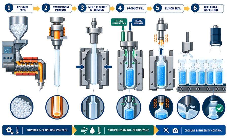
A typical BFS cycle includes:
- Supplying qualified polymer resin to the extruder
- Heating and extruding the polymer into a tubular parison
- Closing the mold around the parison
- Forming the container with filtered gas or vacuum
- Filling the newly formed container through the filling mandrel
- Withdrawing the mandrel
- Fusion-sealing the container
- Opening the mold and discharging the unit
- Removing flash and separating individual containers when applicable
- Inspecting the container, fill, seal, and coded information
The steps occur in rapid sequence, but each has distinct failure modes. Extrusion conditions affect polymer sterilization, wall thickness, particles, and container geometry. Filling conditions affect volume accuracy and contamination risk. Sealing conditions affect fusion strength and container-closure integrity.
Aseptic and terminally sterilized BFS processes
The sterility-assurance model must be identified before qualification begins.
For an aseptic BFS process, sterile product is filled into the newly formed container and sealed without a subsequent sterilization process capable of providing the required sterility assurance. The product path, filling interfaces, critical processing zones, gases, interventions, and container seal therefore require direct aseptic control.
For a terminally sterilized BFS product, the filled and sealed container is subjected to a validated terminal sterilization cycle. BFS forming, filling, and sealing still require controlled conditions, but qualification must also establish that:
- The container withstands the sterilization cycle
- Container geometry does not prevent sterilant distribution
- The cycle does not compromise seal integrity
- Polymer properties remain acceptable
- Product quality remains within specifications
- The validated cycle covers worst-case load and container configurations
Terminal sterilization is generally preferred when the product and container can withstand an effective process. The justification for aseptic processing should be scientifically documented when terminal sterilization is not suitable.
Shuttle and rotary BFS configurations
BFS equipment does not have one universal contamination-control model.
In a shuttle, or cut-parison, system, the extruded parison is cut and transferred beneath the filling mandrel. Potential exposure points include:
- Cutting the parison
- Transfer beneath the filling mandrel
- Entry and withdrawal of the mandrel
- The interval before fusion sealing
These locations require clearly defined critical-zone protection and justified airflow behavior.
In a rotary, or closed-parison, system, forming and filling occur within an enclosed internal space. The critical filling environment may be less accessible for direct monitoring, making equipment design, filtered gas control, validated operating parameters, indirect monitoring, and intervention control especially important.
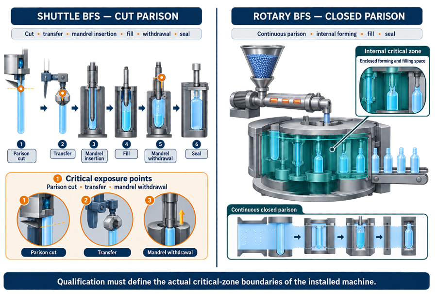
Qualification should define the actual critical zones for the selected machine. It should not describe the entire BFS machine or room as an ISO 5 zone unless the facility design and supporting qualification data justify that classification.
System boundary and interfaces
The BFS qualification boundary should include more than the molding machine. Depending on the installation, the system may include:
- Polymer receipt, storage, sampling, and transfer
- Resin hopper, dryers, vacuum loaders, and conveying lines
- Extruder, heating zones, extrusion head, and parison controls
- Molds, mold cooling, vacuum, and forming-gas systems
- Product holding vessel and transfer piping
- Product sterilizing filters and downstream sterile connections
- Filling mandrels, needles, nozzles, and distribution manifolds
- Clean-in-place and steam-in-place circuits
- Process air, nitrogen, vacuum, cooling water, and other utilities
- Critical-zone air treatment and localized protection
- Deflashing, cutting, conveying, coding, and inspection equipment
- Reject devices and reject-reconciliation systems
- Machine controls, recipes, historian interfaces, and electronic records
- Downstream leak testing, visual inspection, and packaging operations
Interfaces should be addressed explicitly. Supporting information is provided in the articles on aseptic filling-line architecture, process gas systems for GMP manufacturing, clean-in-place utility systems, and steam-in-place utility systems.
Regulatory basis
The FDA’s Sterile Drug Products Produced by Aseptic Processing — Current Good Manufacturing Practice includes a BFS appendix. It identifies BFS as an advanced aseptic process but makes clear that the general principles of aseptic processing continue to apply. The guidance highlights exposure points, sterile gas, equipment design, environmental control, and final examination for container defects and leakers.
Applicable US CGMP provisions include:
- 21 CFR 211.42 — Design and construction features
- 21 CFR 211.63 — Equipment design, size, and location
- 21 CFR 211.65 — Equipment construction
- 21 CFR 211.67 — Equipment cleaning and maintenance
- 21 CFR 211.68 — Automatic, mechanical, and electronic equipment
- 21 CFR 211.94 — Drug product containers and closures
- 21 CFR 211.100 — Written procedures and deviations
- 21 CFR 211.110 — Sampling and testing of in-process materials and products
- 21 CFR 211.113 — Control of microbiological contamination
- 21 CFR 211.192 — Production record review and investigations
The FDA’s final Container Closure Systems for Packaging Human Drugs and Biologics provides additional expectations for protection, compatibility, safety, and performance.
For globally supplied products, the European Commission’s EU GMP Annex 1: Manufacture of Sterile Medicinal Products contains specific BFS provisions in paragraphs 8.105–8.120.
USP chapters applicable to the product and container system should be identified in the site’s regulatory assessment. These may include chapters addressing sterility, bacterial endotoxins, particulate matter, plastic packaging systems, extractables and leachables, and package integrity.
Intended use and user requirements
The user requirements specification should define the intended products, containers, operating modes, and compliance expectations. Important requirements include:
- Aseptic or terminally sterilized operation
- Product types, strengths, viscosities, and temperature limits
- Resin grades, additives, colors, and approved suppliers
- Container shapes, nominal volumes, and dimensional tolerances
- Maximum campaign duration and planned production rate
- Product-contact materials and surface requirements
- Cleaning, sterilization, and hold-time requirements
- Product and forming-gas filtration
- Critical-zone conditions
- Environmental and process monitoring
- Fill-volume accuracy
- Wall-thickness and seal requirements
- Container-closure integrity expectations
- Inspection, rejection, and reconciliation
- Recipe management and electronic-record controls
- Maintenance access and intervention restrictions
- Alarm, interlock, and fail-safe behavior
Requirements should be traceable through design review, qualification testing, procedures, training, and routine monitoring.
Polymer and extrusion controls
The polymer is both a raw material and the material from which the primary container is formed. Controls should address:
- Resin identity and approved grade
- Supplier qualification and change notification
- Additives, colorants, lubricants, and processing aids
- Storage temperature and humidity
- Protection from particulate and microbial contamination
- Resin transfer and hopper cleanliness
- Lot traceability and reconciliation
- Regrind prohibition or controlled use, when applicable
- Polymer bioburden
- Endotoxin or pyrogen risk when relevant
- Extrusion temperature, pressure, speed, and residence time
High extrusion temperature may contribute to the microbiological control of the molded container. That contribution should be demonstrated under defined worst-case conditions rather than assumed. Qualification should evaluate cold starts, temperature distribution, minimum residence time, planned pauses, restarts, and the consequences of operation outside the validated extrusion range.
Extrusion qualification should also address degraded polymer, gels, black specks, incomplete melting, foreign particles, variable parison thickness, and thermal damage.
Product path, cleaning, and sterilization
The product path commonly includes a holding vessel, transfer piping, sterilizing filter, distribution manifold, and filling mandrels. Its qualification should establish:
- Complete and repeatable cleaning
- Cleaning-agent removal
- Sterilization coverage
- Temperature distribution and minimum lethality
- Drainability and condensate removal
- Pre- and post-sterilization hold times
- Sterile hold time
- Filter installation and wetting
- Pre-use and post-use integrity testing, where required
- Sterile connection and disconnection controls
- Protection following sterilization
- Recovery after an interrupted cleaning or sterilization cycle
Related lifecycle controls are discussed in sterile filter integrity and lifecycle control.
Forming and process gases
Gas contacting the internal container surface or product should have defined chemical, particulate, and microbiological quality. Qualification should cover:
- Gas source and distribution
- Point-of-use filtration
- Filter rating and compatibility
- Filter integrity or effectiveness verification
- Pressure, flow, temperature, and dew point where relevant
- Backflow prevention
- Alarm and interlock limits
- Maintenance and replacement frequencies
- Sampling locations and monitoring methods
The qualification rationale should distinguish forming gas, sterile product-contact gas, instrument air, and utility air. They should not be treated as equivalent merely because they originate from a common system.
Critical zones and environmental control
The critical-zone strategy should be based on the machine configuration and actual contamination pathways. The assessment should consider:
- Open or cut parison surfaces
- Filling-mandrel entry and withdrawal
- Product outlet exposure
- Time between filling and sealing
- Airflow around molds and moving parts
- Heat generated by extrusion
- Cooling-air disturbances
- Machine openings and access panels
- Planned and unplanned interventions
- Air-filter location and protection
- Activities performed immediately after a stop
Airflow visualization studies should demonstrate protection during representative dynamic conditions, including machine motion and permitted interventions. Smoke selection, camera placement, lighting, and study execution should avoid introducing residue or obscuring the critical zone.
Nonviable and viable monitoring should be risk-based and compatible with machine design. Where direct access to a critical filling zone is restricted, the control strategy may rely more heavily on design qualification, airflow evidence, filtered-gas verification, process monitoring, APS results, and qualified indirect monitoring locations. The limitations and rationale should be documented.
See environmental monitoring for aseptic filling for program design and investigation principles.
Materials compatibility and product protection
The BFS container should protect the product throughout its shelf life. The assessment should consider:
- Extractables and leachables
- Polymer additives and supplier changes
- Product adsorption or absorption
- Moisture-vapor transmission
- Oxygen permeability
- Light transmission
- Container deformation
- Stress cracking
- Interaction with labels, inks, and secondary packaging
- Shipping and distribution stresses
- Effects of terminal sterilization
- Effects of storage temperature and time
Compatibility cannot be established through dimensional inspection alone. Product stability, container performance, and material characterization should be connected to the qualified manufacturing range.
Critical parameters and operating ranges
A science- and risk-based assessment should identify the parameters that influence sterility assurance, container formation, fill accuracy, and sealing. Typical parameters include:
- Extruder-zone temperatures
- Melt temperature and pressure
- Extrusion speed
- Parison programming and thickness
- Parison cut and transfer timing
- Mold temperature
- Cooling-water temperature and flow
- Forming-gas pressure and time
- Vacuum level
- Mandrel position and timing
- Fill volume, speed, and duration
- Product temperature and viscosity
- Fusion-seal temperature, pressure, and dwell time
- Mold-closing force
- Cycle time
- Product and gas filter differential pressure
- Clean-in-place and steam-in-place parameters
- Critical-zone airflow or pressure indicators
Setpoints, normal operating ranges, proven acceptable ranges, alarms, interlocks, and response procedures should be distinguishable. Qualification should challenge meaningful operating edges and interactions rather than merely record nominal conditions.
Qualification strategy
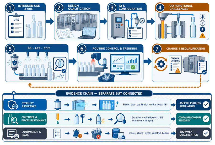
BFS qualification should connect equipment evidence with sterility assurance, product-path control, container performance, and automated-system control.
Design qualification
Design qualification should confirm that the selected machine can meet the intended process and compliance requirements. Reviews should include:
- BFS configuration and critical-zone concept
- Product and gas flow paths
- Hygienic design and drainability
- Cleaning and sterilization coverage
- Mold and tooling design
- Container geometry and seal formation
- Utility capacities
- Airflow and heat-load management
- Monitoring provisions
- Accessibility and intervention controls
- Inspection and reject systems
- Software architecture and data retention
- Maintenance strategy
- Supplier documentation and support
Installation qualification
Installation qualification should verify the installed configuration against approved drawings and specifications. Verification normally includes:
- Equipment identification
- Materials of construction
- Piping, instrumentation, and utility connections
- Filters and flow direction
- Sensors, transmitters, and calibration status
- Mold and tooling identification
- Software and firmware versions
- Electrical and control-panel configuration
- Safety devices
- Spare parts and lubricants
- Manuals, drawings, and certificates
Operational qualification
Operational qualification should challenge functions throughout the intended operating range. Testing should include:
- Startup and shutdown sequences
- Recipe selection and parameter protection
- Extrusion-zone control
- Mold motion and timing
- Filling accuracy
- Seal formation
- Utility failures
- Alarm and interlock challenges
- Sensor failures
- Communication failures
- Reject-device operation
- Reject confirmation and reconciliation
- Emergency stops and recovery
- Power-loss recovery
- Cleaning and sterilization cycles
- Electronic-record and audit-trail functions where applicable
Performance qualification
Performance qualification should demonstrate repeatable operation with representative products, resins, molds, containers, rates, and campaign conditions. The protocol should define bracketing and matrixing scientifically.
PQ should assess:
- Container dimensions and appearance
- Wall-thickness distribution
- Fill-volume accuracy and uniformity
- Seal quality
- Container-closure integrity
- Particulate and visual defects
- Critical process parameters
- Startup and end-of-run conditions
- Maximum planned operating duration
- Representative interventions
- Reject-system performance
- Yield and defect trends
The fill-line qualification lifecycle provides complementary principles for qualification planning and continued verification.
Aseptic process simulation
Aseptic BFS processes require a qualified aseptic process simulation program. The simulation should represent or challenge:
- Routine startup
- Maximum justified campaign duration
- Normal operating speed and justified speed extremes
- Operator shifts and staffing
- Product-path assembly
- Sterile filter connections
- Planned interventions
- Rare but permitted interventions
- Machine stops and pauses
- Restart following a stop
- Mandrel or filling-zone access
- Container sampling
- Environmental monitoring activities
- End-of-run conditions
Interventions that stop extrusion, forming, filling, or sealing should be defined. The required recovery, re-sterilization, line clearance, and product disposition should be reflected in procedures and challenged when relevant.
The medium should support growth while remaining suitable for BFS processing and inspection. Container opacity, coloration, shape, or surface texture should not prevent reliable detection of growth. When direct visual detection is difficult, an alternative validated examination strategy may be necessary.
See media fill and aseptic process simulation for program design, incubation, inspection, and investigation requirements.
Container integrity and defect control
The BFS container and its fusion seal are produced by the manufacturing process itself. Container qualification and process qualification are therefore closely connected.
Potential defects include:
- Thin or uneven walls
- Pinholes and microchannels
- Weak fusion seals
- Incomplete sealing
- Distorted necks or ports
- Inclusions, gels, and black specks
- Flash interfering with the seal or container
- Incorrect fill volume
- Damaged opening features
- Illegible or incorrect coding
- Deformation during handling or terminal sterilization
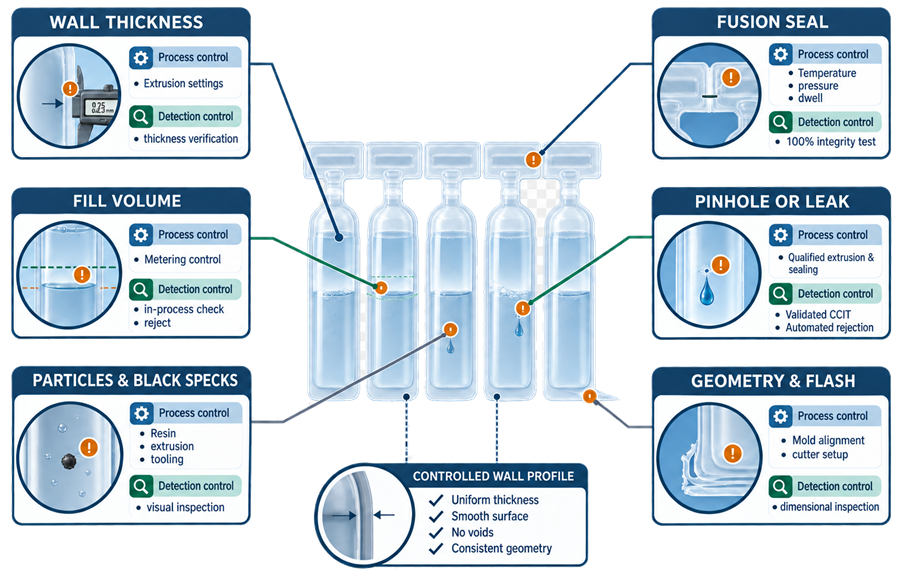
Qualification should address wall thickness at vulnerable locations such as corners, shoulders, necks, ports, and seams. Fusion-seal studies should evaluate suitable combinations of temperature, pressure, timing, mold condition, cooling, and material properties.
Container-closure integrity testing should use a method suitable for the container, product, defect type, and required sensitivity. Method validation should address detection limit, positive and negative controls, sample preparation, container variability, and the effects of product or headspace.
The container closure integrity testing article discusses deterministic and probabilistic methods and lifecycle application.
Visual inspection, seal inspection, and container-closure integrity testing provide different evidence:
- Visual inspection detects observable cosmetic and functional defects.
- Seal inspection evaluates the formed seal and its geometry or strength.
- Integrity testing evaluates the package’s ability to prevent leakage or microbial ingress.
A claim of 100% visual inspection should not be represented as 100% container-closure integrity testing. Where 100% integrity testing is implemented, the validated test method, sensitivity, reject system, challenge frequency, and data review should be specified.
Computerized controls and data integrity
BFS automation commonly manages recipes, sequence control, alarms, rejects, parameter records, and interfaces with site systems. Qualification should address:
- User access and role assignment
- Recipe creation, approval, and modification
- Setpoint and limit protection
- Alarm generation, acknowledgment, and retention
- Interlock logic
- Audit trails when applicable
- Electronic signatures when applicable
- Batch and parameter reports
- Reject counts and reconciliation
- Date and time synchronization
- Data transfer and interface failure
- Backup and restoration
- System restart and disaster recovery
- Retention of records required for investigations
The validation scope should reflect the system’s influence on product quality, sterility assurance, container integrity, and batch disposition.
Routine operation and batch review
Routine procedures should define:
- Line clearance
- Resin and product verification
- Mold and recipe verification
- Cleaning and sterilization status
- Filter status
- Startup checks and startup rejects
- Required environmental and process monitoring
- In-process sampling
- Parameter review
- Defect classification
- Reject handling and reconciliation
- Response to alarms and interventions
- End-of-run clearance
- Batch-record review and release
Batch review should consider parameter excursions, alarms, machine stops, interventions, rejected units, visual-defect trends, integrity-test results, environmental observations, and filter-integrity results as a connected body of evidence.
Deviations and investigations
BFS investigations should reconstruct the timing and extent of the event. Useful information may include:
- Machine-state history
- Parameter trends
- Alarm and interlock records
- Operator actions
- Video or intervention records where available
- Environmental-monitoring results
- Reject counts and defect images
- Mold, cavity, and lane identification
- Resin and product lot information
- Maintenance history
- Calibration status
- Filter-integrity results
- Container-integrity testing
Investigations should consider whether potentially affected units can be bounded reliably. Repeated defects should be trended by mold, cavity, lane, mandrel, seal position, resin lot, shift, and campaign stage when those data are available.
Continued process verification
Continued verification should demonstrate that the qualified BFS process remains controlled. Trending may include:
- Extrusion temperatures and pressures
- Cycle time
- Parison-thickness indicators
- Wall-thickness measurements
- Fill-volume results
- Seal measurements
- Integrity-test failures
- Visual-defect categories
- Reject rate
- Mold- or cavity-specific defects
- Filter-integrity results
- Environmental and process-monitoring results
- Alarm frequency
- Intervention frequency
- Unplanned stops
- Maintenance frequency
- Resin and supplier changes
Alert and action criteria should be based on process understanding and sufficient historical data. Adverse trends should be investigated before they become specification failures.
Maintenance and calibration
The maintenance program should account for components capable of affecting sterility or container integrity, including:
- Extruder screws, barrels, heaters, and temperature sensors
- Extrusion heads and parison-control components
- Molds and cooling channels
- Filling mandrels and seals
- Fusion-sealing surfaces
- Cutters and deflashing equipment
- Product and gas filters
- Pressure, flow, temperature, and position sensors
- Cameras and inspection systems
- Reject mechanisms
Post-maintenance verification should be proportionate to the work performed. Intrusive maintenance near sterile product paths, critical zones, molds, mandrels, or sealing components may require cleaning, sterilization, functional testing, container evaluation, environmental recovery, or requalification before production resumes.
Change control and requalification
Changes that may affect the qualified state include:
- New resin grade or supplier
- Polymer additive or formulation change
- New container design or nominal volume
- Mold replacement, repair, or modification
- Extrusion-head or screw change
- New product formulation
- Change in product temperature or viscosity
- Fill-speed or cycle-time change
- Critical-zone or air-handling modification
- Product-path modification
- New filter type
- Software, recipe, or control-logic change
- Inspection-method or reject-system change
- Increased campaign duration
- Terminal sterilization-cycle change
- Major maintenance or equipment relocation
A formal change-control impact assessment should determine the required document updates, testing, studies, APS, stability work, regulatory assessment, and requalification. Risk-based requalification may be used when the rationale, affected functions, acceptance criteria, and retained evidence are documented.
Mold changes deserve particular attention because they can alter wall thickness, container geometry, seal formation, cooling behavior, fill position, downstream handling, and inspection-system performance.
Common qualification deficiencies
Common deficiencies include:
- Treating BFS as inherently sterile because the process is automated
- Failing to distinguish aseptic from terminally sterilized operation
- Applying one critical-zone model to all BFS machine types
- Claiming the entire machine is ISO 5 without supporting evidence
- Assuming extrusion temperature sterilizes the polymer without validation
- Omitting polymer bioburden or endotoxin risk
- Failing to qualify product-contact or forming gases
- Performing airflow studies only with the machine idle
- Excluding stops, interventions, and restarts from APS
- Qualifying nominal settings without operating-range challenges
- Evaluating average wall thickness but not vulnerable locations
- Treating visual inspection as container-closure integrity testing
- Failing to trend defects by mold, cavity, lane, or mandrel
- Changing molds or resin without appropriate impact assessment
- Reviewing machine alarms separately from batch-quality evidence
- Inadequate reject-system challenge and reconciliation
- Insufficient post-maintenance verification
Conclusion
A BFS machine integrates container formation, filling, and sealing, but the qualification program should retain clear evidence for each critical function. Reliable lifecycle control depends on connecting polymer management, extrusion, sterile product delivery, critical-zone protection, forming and sealing, container integrity, automated controls, inspection, and continued monitoring.
A well-designed program defines the sterility-assurance model, distinguishes the machine configuration, challenges meaningful operating ranges, represents interventions in APS, validates container performance, and uses routine data to detect deterioration before product quality is affected.