

Filtration and Ultrafilation System Architecture
Filtration and ultrafiltration systems are integrated process systems used to separate particles, microorganisms, cells, viruses, macromolecules, solvents, and dissolved low-molecular-weight species. Their architecture depends on the intended separation, product characteristics, processing scale, contamination-control requirements, and operating strategy.
A filtration system is not limited to the filter or membrane. The complete system may include feed and collection vessels, pumps, membrane modules, pressure-control devices, valves, tubing or piping, instruments, automation, utilities, cleaning or disposable-flow-path provisions, and interfaces with upstream and downstream equipment.
System architecture establishes how material enters, moves through, exits, and is recovered from the filtration process. It also determines which pressures, flows, temperatures, volumes, and quality attributes can be controlled or monitored.
Purpose and Lifecycle Position
This article addresses the system-level architecture of filtration and ultrafiltration equipment used in pharmaceutical and biopharmaceutical manufacturing. It covers:
- Intended use and separation objectives
- Normal-flow and tangential-flow architectures
- Feed, retentate, permeate, and filtrate pathways
- Ultrafiltration and diafiltration operating modes
- System boundaries and process interfaces
- Pressure, flow, volume, and temperature-control architecture
- Instrumentation and automation boundaries
- Reusable, single-use, and hybrid configurations
- Cleaning, sanitization, sterilization, and contamination-control interfaces
- Architectural risks and design-review considerations
- Relationship to equipment qualification and process validation
Detailed membrane, pump, valve, housing, sensor, and material-selection considerations are addressed in Filtration System Design and Critical Components.
Formal DQ, IQ, OQ, equipment-level PQ, software verification, lifecycle review, and requalification are addressed in Filtration Skid Qualification and Lifecycle Control.
Process-specific studies for clarification, tangential-flow filtration, and virus filtration are addressed in Bioprocess Filtration Validation: Clarification, TFF, and Virus Filtration.
Sterilizing-grade filtration, bacterial-retention studies, filter-integrity testing, product compatibility, maximum filtration time, and sterile hold time are addressed separately in Sterilizing Filtration Validation and Sterile Hold-Time Control.
Intended Use Determines System Architecture
The intended use should be established before selecting the membrane, module, skid, instruments, or automation platform. The same equipment configuration is not appropriate for every filtration application.
The intended-use definition should identify:
- Material being processed
- Required separation
- Material that must be retained
- Material that must pass through the membrane
- Required product recovery
- Batch size and concentration
- Product viscosity and shear sensitivity
- Initial particulate or bioburden load
- Required processing time
- Temperature limitations
- Maximum permissible pressure
- Cleaning, sanitization, or sterilization requirements
- Single-use or reuse strategy
- Required operating records
- Interfaces with upstream and downstream operations
A system used for harvest clarification has different hydraulic, fouling, and solids-handling requirements from a system used to concentrate a purified protein. A virus-retentive filter may use normal-flow architecture but require more restrictive pressure, throughput, prefiltration, and integrity controls. A sterilizing-filtration system requires additional controls associated with the sterile boundary and aseptic processing.
Common Filtration Applications
| Application | Typical separation objective | Common architecture | Principal controlled pathways |
|---|---|---|---|
| Depth clarification | Remove cells, debris, or precipitated material | Normal-flow filtration | Feed and filtrate |
| Membrane clarification | Remove fine particles or reduce turbidity | Normal-flow or tangential flow | Feed, filtrate or permeate, and sometimes retentate |
| Bioburden-reduction filtration | Reduce microbial load before a subsequent process step | Normal-flow filtration | Feed and filtrate |
| Sterilizing-grade filtration | Produce a sterile filtrate within a validated aseptic process | Normal-flow filtration | Product feed and sterile filtrate |
| Virus filtration | Retain virus particles while recovering product | Commonly normal-flow filtration | Feed and virus-filtered product |
| Ultrafiltration | Concentrate retained macromolecules | Tangential-flow filtration | Feed, retentate, and permeate |
| Diafiltration | Exchange buffer or remove permeable solutes | Tangential-flow filtration | Retentate, permeate, and diafiltration-buffer addition |
| Cell retention or perfusion | Retain cells while removing or exchanging liquid | Tangential-flow or alternating-flow architecture | Cell-containing retentate and permeate |
These are typical arrangements, not universal rules. Final architecture should be justified for the actual product and separation mechanism.
Normal-Flow and Tangential-Flow Filtration
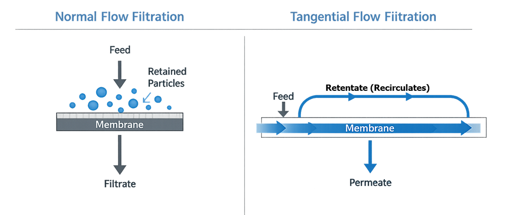
The main architectural distinction is the direction of feed movement relative to the membrane and the disposition of retained material. The following comparison shows the linear feed-to-filtrate pathway of normal-flow filtration and the recirculating retentate and separate permeate pathways of tangential-flow filtration.
Normal-Flow Filtration
In normal-flow filtration, also called dead-end filtration, feed is dalt irected generally toward and through the filter medium. Filtrate passes through the filter, while retained material accumulates on the surface or within the depth of the filter.
A basic normal-flow pathway may be represented as:
Feed vessel → Pump or pressure source → Prefilter → Final filter → Filtrate vessel
Depending on the application, the architecture may include:
- Multiple filters in series
- Parallel filter trains
- Redundant filters
- Vent and drain connections
- Differential-pressure measurement
- Upstream and downstream sampling
- Integrity-test connections
- Bypass prevention
- Filter-heating or temperature-control provisions
- Sterile connections and a protected downstream pathway
As retained material accumulates, resistance normally increases. The system should be capable of detecting or controlling the resulting change in differential pressure, flow, or processing time.
Normal-flow architecture is commonly used for:
- Depth filtration
- Clarification
- Prefiltration
- Bioburden reduction
- Sterilizing-grade filtration
- Virus filtration
- Buffer and media filtration
A reusable normal-flow filtration arrangement may use a sanitary stainless-steel housing installed between the product-feed and filtrate pathways.
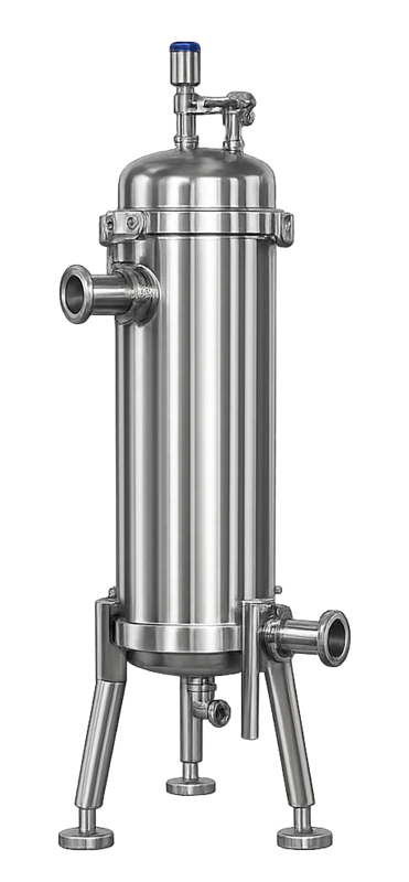
The design should establish whether filtration is controlled primarily by flow, upstream pressure, differential pressure, processing time, throughput, or a combination of these parameters.
Tangential-Flow Filtration
In tangential-flow filtration, feed travels parallel to the membrane surface. A portion passes through the membrane as permeate, while the retained stream continues along the membrane surface as retentate.
The retentate normally returns to the feed vessel or recirculation loop. This creates two distinct outlet pathways:
- Permeate: Material passing through the membrane
- Retentate: Material retained by the membrane and returned or recovered
A typical TFF pathway may be represented as:
Feed vessel → Recirculation pump → Membrane module → Retentate return to feed vessel
with a separate:
Membrane module → Permeate line → Permeate collection or waste
Tangential flow helps limit accumulation directly on the membrane surface, but it does not eliminate fouling. Fouling behavior still depends on the product, membrane, concentration, crossflow conditions, temperature, processing time, and cleaning or reuse history.
TFF is used for:
- Protein concentration
- Buffer exchange
- Removal of salts or low-molecular-weight impurities
- Cell concentration
- Product recovery from process streams
- Selected microfiltration applications
- Continuous or intensified bioprocessing applications
Not every TFF system is an ultrafiltration system. TFF describes the flow regime. Ultrafiltration describes a membrane-separation range. Tangential-flow microfiltration and other crossflow applications also exist.
Ultrafiltration and Molecular-Weight Cutoff
Ultrafiltration membranes are commonly characterized by molecular-weight cutoff, or MWCO. The designation provides a comparative indication of membrane retention behavior under specified test conditions.
MWCO should not be interpreted as an absolute boundary at which every molecule above the stated value is retained and every smaller molecule passes through. Actual retention can be influenced by:
- Molecular shape
- Molecular charge
- Product aggregation
- Membrane material
- Pore-size distribution
- Concentration polarization
- Product concentration
- Buffer composition
- Ionic strength
- Temperature
- Transmembrane pressure
- Crossflow conditions
- Membrane fouling
Membrane selection should therefore be supported by development or process-characterization data rather than by MWCO designation alone.
The ultrafiltration membrane should retain the desired product while allowing the required solvent and smaller components to pass into the permeate. The selected membrane area and system volume should also support acceptable processing time and product recovery.
Core TFF System Architecture
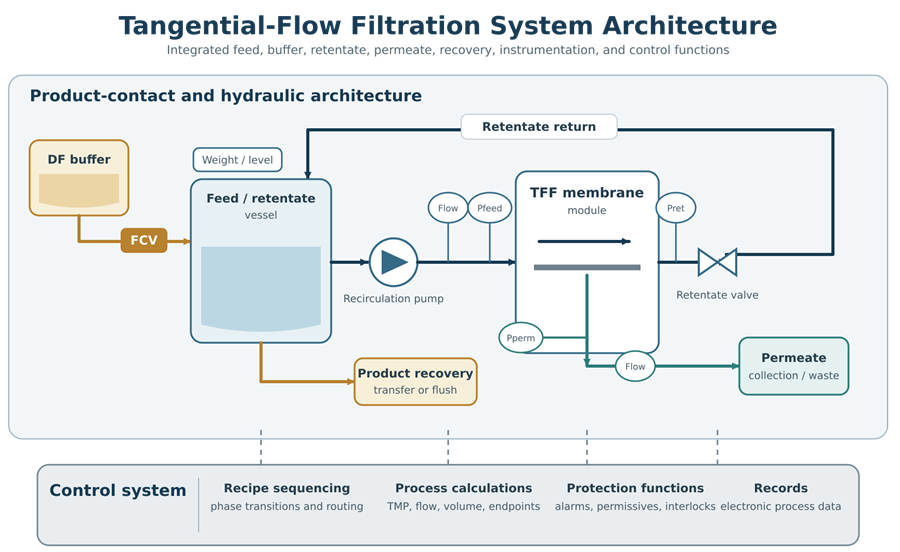
A TFF system usually includes several coordinated functional zones. A reusable normal-flow filtration arrangement may use a sanitary stainless-steel housing installed between the product-feed and filtrate pathways.
Feed and Retentate Zone
The feed vessel contains the starting material and receives the returning retentate. Its design may include:
- Agitation or controlled mixing
- Temperature control
- Load cells or level measurement
- Feed and buffer-addition connections
- Retentate-return connection
- Sampling
- Vent filtration
- Drain and product-recovery connections
- Spray devices where cleaning is required
The vessel and return arrangement should minimize foaming, air entrainment, localized concentration, and unnecessary product hold-up.
Recirculation Zone
The recirculation loop moves material from the feed vessel through the membrane and back to the vessel. It commonly includes:
- Recirculation pump
- Feed-pressure instrument
- Flow measurement
- Temperature measurement
- Membrane module
- Retentate-pressure instrument
- Retentate control valve
- Return piping or tubing
The loop should provide the required crossflow while limiting excessive shear, temperature rise, foaming, and product residence time.
Permeate Zone
The permeate pathway removes liquid and permeable species from the system. It may include:
- Permeate-pressure measurement
- Permeate-flow measurement
- Conductivity or other inline analysis
- Permeate control valve
- Sampling point
- Collection vessel
- Waste routing
- Return or recirculation capability where required
The design should prevent unintended backpressure, backflow, cross-connection, or incorrect routing of permeate.
Buffer-Addition Zone
Diafiltration requires controlled addition of diafiltration buffer. Buffer may be supplied through:
- A dedicated buffer vessel
- A controlled transfer line
- A metering pump
- A flow-control loop
- Vessel-weight control
- Level control
The architecture should coordinate buffer addition with permeate removal. Failure of this coordination can alter concentration, process volume, TMP, and diafiltration performance.
Product-Recovery Zone
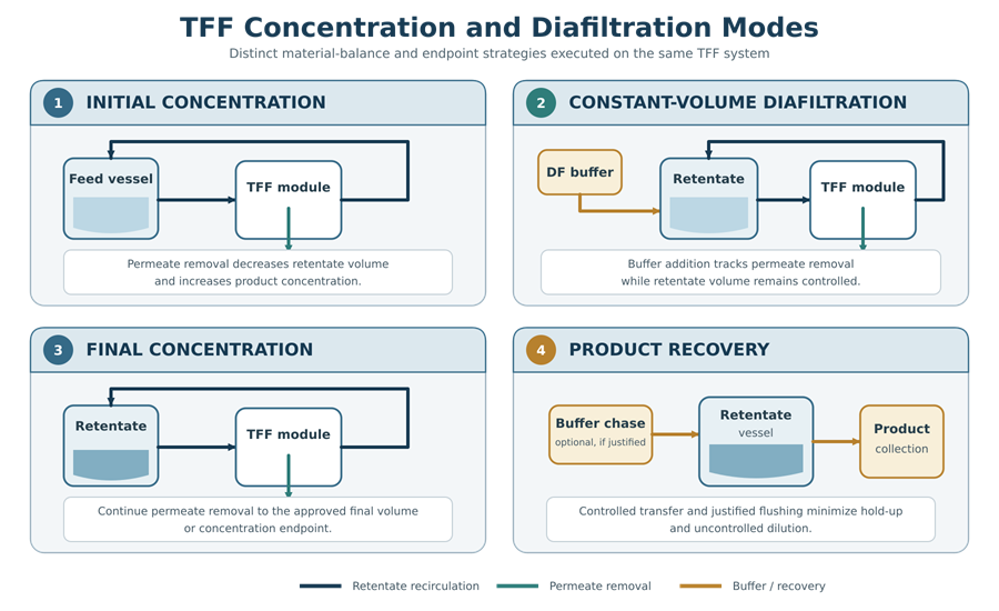
Product remains within the retentate pathway. Recovery provisions may include:
- Controlled drain or transfer from the feed vessel
- Retentate displacement
- Buffer flush
- Air or gas displacement where justified
- Low-point recovery connections
- Product-recovery pump
- Recovery to another vessel or processing skid
The recovery sequence should be designed to minimize product loss without introducing uncontrolled dilution, air exposure, contamination, or excessive shear.
TFF Operating Modes
A TFF skid may use the same equipment to execute several distinct operating modes. Although the primary equipment remains unchanged, valve routing, buffer addition, permeate removal, material balance, and endpoint control differ among concentration, diafiltration, and recovery phases.
System Preparation
Preparation may include:
- Disposable assembly installation
- Membrane installation
- Connection verification
- Flushing
- Membrane conditioning
- Water permeability or normalized water permeability testing
- Leak or integrity testing
- Air removal
- Instrument zeroing or tare functions
- Line clearance
- Recipe and material verification
Preparation requirements depend on membrane type, supplier instructions, reuse strategy, and process criticality.
Concentration
During concentration, permeate is removed without an equivalent replacement volume. The retentate volume decreases and retained product concentration increases.
The concentration endpoint may be based on:
- Vessel weight
- Vessel level
- Calculated volume
- Concentration factor
- Product concentration
- Permeate volume
- Processing time
- Another justified process endpoint
Constant-Volume Diafiltration
During constant-volume diafiltration, buffer is added at approximately the same rate that permeate is removed. Retentate volume remains within a defined range while permeable solutes are exchanged or removed.
Control may be based on:
- Matched buffer and permeate flow
- Vessel weight
- Vessel level
- Totalized permeate volume
- Totalized buffer volume
- Conductivity or another analytical endpoint
Discontinuous Diafiltration
In discontinuous or batch diafiltration, the material is concentrated, diluted with diafiltration buffer, and concentrated again. The sequence may be repeated until the required exchange is achieved.
This method uses different volume and control logic from constant-volume diafiltration and should not be treated as interchangeable without process evaluation.
Final Concentration
After diafiltration, the product may undergo final concentration to its required target. Product viscosity and hydraulic resistance may increase significantly during this phase.
The system should remain within established limits for:
- TMP
- Crossflow
- Feed and retentate pressure
- Flux
- Temperature
- Pump speed
- Product concentration
- Processing time
Recovery and Post-Use Processing
After product recovery, the system may proceed to:
- Product-recovery flush
- Water or buffer displacement
- Membrane rinsing
- Cleaning
- Sanitization
- Storage-solution introduction
- Draining
- Disposable assembly removal
- Membrane preservation
- Post-use integrity or permeability testing
The selected sequence depends on whether the flow path and membrane are reused or discarded.
Hydraulic and Pressure-Control Architecture
Hydraulic control is central to filtration-system design. The system should be capable of operating within the allowable pressure ratings of the membrane, housing, tubing, connections, instruments, and downstream equipment.
Differential Pressure
For normal-flow filtration:
Differential pressure = Upstream pressure − Downstream pressure
Differential pressure indicates resistance across the filter assembly. Increasing differential pressure at an equivalent flow or throughput may indicate loading, fouling, blockage, or an abnormal flow restriction.
Transmembrane Pressure
For many TFF applications, TMP is estimated as:
TMP = ((Feed pressure + Retentate pressure) / 2) − Permeate pressure Where:
- Feed pressure is measured at or near the membrane inlet.
- Retentate pressure is measured at or near the membrane outlet.
- Permeate pressure is measured in the permeate pathway.
This equation uses the average of the feed and retentate pressures as an approximation of average pressure on the retentate side. The approved calculation should follow the selected system and membrane supplier’s defined convention.
Permeate pressure should not automatically be assumed to be zero. Tubing restrictions, valves, filters, elevation, collection-vessel pressure, or closed permeate pathways can create measurable permeate backpressure.
Module Pressure Drop
Pressure drop through the retentate pathway may be expressed as:
Module pressure drop = Feed pressure − Retentate pressure
Module pressure drop is related to crossflow, viscosity, module geometry, concentration, and flow-path restriction. Excessive pressure drop may indicate blockage, excessive viscosity, inappropriate flow, membrane compression, or another abnormal condition.
Flux
Permeate flux may be expressed as:
Flux = Permeate flow rate / Effective membrane area
Flux allows comparison of permeate performance after accounting for membrane area. Interpretation should consider product concentration, temperature, TMP, membrane history, and process phase.
The formulas do not establish acceptable operating limits. Limits should be supported by system capability, membrane requirements, process development, product studies, and validation evidence.
Pressure and Flow-Control Strategies
Different systems use different control strategies. Examples include:
- Fixed recirculation-pump speed
- Controlled crossflow rate
- Controlled feed pressure
- Controlled retentate pressure
- Controlled TMP
- Controlled permeate flow
- Controlled permeate pressure
- Coordinated feed and retentate control
- Coordinated buffer-addition and permeate-removal control
A retentate valve may be used to create and control backpressure. Permeate control may be passive or actively regulated. Some systems use feed-flow control with pressure monitoring; others use pressure control with flow monitoring.
The control strategy should avoid competing control loops. For example, simultaneously aggressive feed-pressure, retentate-pressure, and TMP control can create unstable valve and pump responses if the loops are not properly coordinated.
Pressure-relief devices, software limits, alarms, interlocks, and pump shutdown functions should protect the system against credible overpressure conditions. Protection should consider blocked outlets, closed valves, incorrect assembly, rapid viscosity increase, loss of permeate flow, and automation failure.
Instrumentation and Automation Architecture
Instrumentation should be selected and located according to the decisions supported by each measurement.
Typical filtration-system measurements include:
- Feed pressure
- Retentate pressure
- Permeate pressure
- Differential pressure
- Feed or recirculation flow
- Permeate flow
- Buffer-addition flow
- Temperature
- Vessel weight
- Vessel level
- Conductivity
- pH
- Turbidity
- UV absorbance
- Pump speed
- Valve position
- Totalized volume
Instrumentation used to control the process, establish acceptance, activate alarms, or support batch disposition should be included in the applicable GMP Calibration Program and Metrology Control.
Automated systems may perform:
- Recipe and phase sequencing
- Pump-speed control
- Valve routing
- TMP calculation
- Differential-pressure calculation
- Flow totalization
- Concentration-factor calculation
- Buffer-addition control
- Diafiltration-volume calculation
- Alarm and interlock execution
- Endpoint determination
- Electronic batch-record generation
- Data transfer to supervisory or manufacturing systems
The automation boundary should identify:
- PLC or controller
- Human-machine interface
- Local instruments
- Variable-frequency drives
- Remote input/output
- Skid software
- Recipe database
- Historian
- Electronic batch-record interface
- Manufacturing execution system interface
- Network and time-synchronization dependencies
- Backup and recovery responsibilities
The design review should determine which values are directly measured and which are calculated. Calculated values should have defined formulas, units, source tags, update frequency, rounding, alarm behavior, and verification requirements.
Reusable, Single-Use, and Hybrid Architecture
Reusable Systems
Reusable filtration systems may include stainless-steel vessels, housings, piping, valves, and membrane holders.
Their architecture should support:
- Cleaning and rinsing
- Sanitization or sterilization where required
- Drainability
- Venting
- Controlled chemical exposure
- Membrane removal or preservation
- Inspection and maintenance
- Reassembly verification
- Defined storage conditions
- Reuse tracking
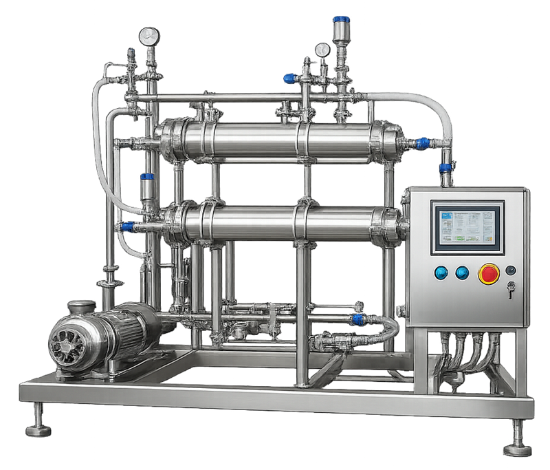
Reusable architecture increases the importance of cleanability, chemical compatibility, surface condition, gasket control, cleaning validation, and cumulative exposure history. A reusable TFF skid typically integrates permanent stainless-steel product pathways, a recirculation pump, membrane holders, instruments, valves, and cleaning connections on a common frame.
Single-Use Systems
Single-use systems may use disposable bags, tubing, connectors, pump tubing, capsule filters, membrane modules, manifolds, and sampling assemblies.
Their controls shift toward:
- Approved assembly configuration
- Supplier qualification
- Material and component traceability
- Sterilization documentation where applicable
- Packaging and shipping integrity
- Expiration or use-by period
- Storage conditions
- Extractables and leachables assessment
- Product compatibility
- Assembly inspection
- Connection verification
- Leak and integrity control
- Prevention of kinks and occlusions
- Disposal and reconciliation
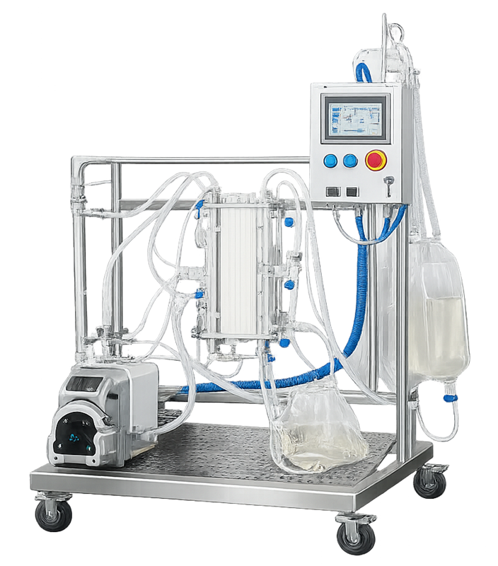
Single-use designation does not establish sterility. It also does not eliminate equipment qualification, supplier control, installation verification, or process validation. In a single-use TFF configuration, the permanent frame, drive equipment, instruments, and automation support a disposable product-contact assembly installed for the manufacturing operation.
Hybrid Systems
Hybrid systems combine reusable equipment with disposable product-contact assemblies. Examples include a reusable control skid with:
- Disposable feed bag
- Peristaltic pump tubing
- Single-use pressure sensors
- Disposable TFF cassette
- Single-use permeate and retentate tubing
- Reusable load cells and automation
The boundary between permanent and disposable elements should be documented. The design should identify which components are qualified once, verified before each use, controlled by supplier documentation, or evaluated through process validation.
Sanitary Design and Contamination Control
Sanitary design should reflect the intended product, microbial risk, reuse strategy, cleaning method, and process stage. Architectural considerations include:
- Product-contact material compatibility
- Smooth and cleanable reusable surfaces
- Appropriate connections and seals
- Minimized hold-up volume
- Drainability
- Venting and air removal
- Prevention of uncontrolled backflow
- Elimination or control of unused branches
- Controlled sampling arrangements
- Protection of open connections
- Prevention of contamination during assembly
- Separation of product, waste, cleaning, and utility pathways
- Protection following cleaning, sanitization, or sterilization
- Defined maximum process and hold times
A system may support reproducible cleaning or sterilization without independently proving that the process is effective. Cleaning validation and sterilization validation require their own acceptance criteria and evidence.
Where a filtration system forms part of an aseptic process, the sterile boundary should identify:
- The sterilizing-grade filter
- Downstream sterile tubing or piping
- Sterile receiving vessel
- Sterile connections
- Sampling points
- Integrity-test connections
- Gas filters
- Hold vessel and transfer pathway
- Boundary termination at the filling system or next sterile operation
Detailed validation of this pathway belongs within the aseptic-processing control strategy.
Utility and Process Interfaces
A filtration skid may interface with:
- Purified Water
- Water for Injection
- Clean steam
- Plant steam
- Clean compressed air
- Nitrogen
- Process gases
- Cooling or heating media
- Electrical power
- Vacuum
- Drain systems
- CIP supply and return
- Upstream vessels
- Downstream vessels
- Buffer systems
- Chromatography systems
- Filling systems
- Automation networks
- Data historians
- Manufacturing execution systems
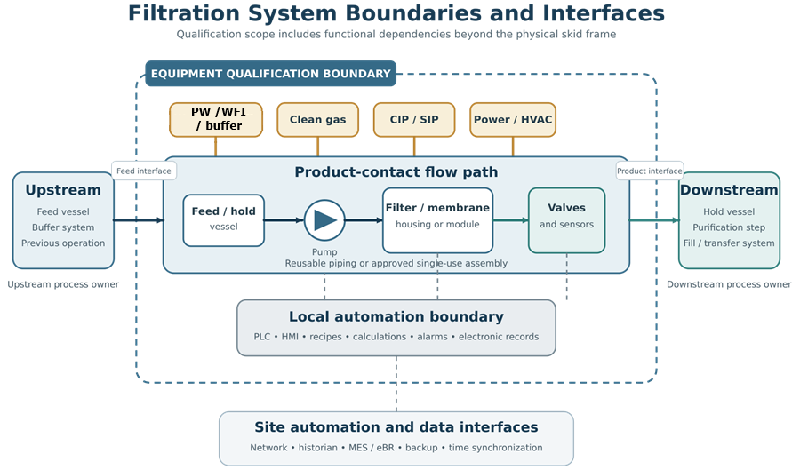
Each interface should have a defined owner, connection point, operating range, quality requirement, and qualification responsibility.
The boundary should distinguish between:
- Equipment supplied as part of the skid
- Site-installed piping and utilities
- Disposable assemblies
- Upstream and downstream process equipment
- Supporting computerized systems
- External data-storage or reporting systems
- Process-validation responsibilities
A skid-frame boundary alone is generally inadequate when essential instruments, vessels, utilities, software, or product pathways extend beyond the physical frame. The system-boundary model below distinguishes the qualified filtration equipment from upstream and downstream process equipment while retaining the utilities, automation, and data interfaces required for system operation.
Architectural Failure Modes
Design review and risk assessment should evaluate credible failures such as:
- Incorrect membrane or assembly installation
- Reversed flow direction
- Incorrect inlet or outlet connection
- Membrane bypass
- Filter rupture
- Excessive differential pressure
- Excessive TMP
- High retentate pressure
- Permeate backpressure
- Pump deadheading
- Closed or incorrectly positioned valve
- Loss of recirculation
- Air entrainment
- Foaming
- Excessive shear
- Product-temperature increase
- Membrane fouling
- Flow-path blockage
- Tubing kink or collapse
- Loss of vessel mixing
- Incorrect buffer addition
- Loss of vessel-weight signal
- Conductivity endpoint failure
- Incorrect permeate routing
- Product loss to waste
- Cross-connection between product and cleaning pathways
- Failure of cleaning, sanitization, or sterilization coverage
- Data loss or incorrect calculation
- Alarm or interlock failure
For each significant failure mode, the architecture should establish suitable prevention, detection, response, and recovery controls.
Design controls may include:
- Physical connection differentiation
- Flow-direction markings
- Recipe permissives
- Valve-position confirmation
- Pressure alarms
- Pump shutdown interlocks
- Independent pressure-relief protection
- Assembly verification
- Line clearance
- Leak testing
- Mass-balance checks
- Conductivity confirmation
- Automated routing verification
- Operator confirmation
- Controlled recovery procedures
Architecture Review and Design Documentation
System architecture should be documented sufficiently to support design review, qualification, operation, maintenance, and change control.
Applicable documentation may include:
- User Requirement Specification
- Process description
- Intended-use statement
- System-boundary drawing
- Process flow diagram
- Piping and instrumentation diagram
- Disposable-assembly drawing
- Equipment and instrument list
- Valve matrix
- Flow-path matrix
- Utility requirements
- Materials-of-construction list
- Instrument specifications
- Control narrative
- Functional specification
- Alarm and interlock list
- Recipe or phase description
- Data-flow diagram
- Network architecture
- Cleaning or disposable-use strategy
- Membrane and filter specifications
- Pressure-rating assessment
- Design-risk assessment
- Requirements traceability matrix
Supplier drawings and manuals may support the design record, but site requirements, process interfaces, intended use, and acceptance decisions should remain under site control.
Relationship to Qualification and Process Validation
Equipment qualification and process validation answer different questions.
Equipment qualification demonstrates that the filtration system:
- Is designed for its intended use
- Is installed according to approved requirements
- Operates across required ranges
- Executes defined control functions
- Provides reliable measurements
- Generates required alarms and interlocks
- Produces accurate calculations and records
- Supports the intended operating sequences
Process validation demonstrates that the filtration operation:
- Achieves the required separation
- Maintains acceptable product quality
- Provides acceptable recovery
- Controls impurities or contaminants
- Operates reproducibly under justified conditions
- Remains within an established operating range
- Continues to perform during routine manufacturing
Equipment qualification does not independently establish membrane retention, product compatibility, viral clearance, microbial retention, product recovery, or process robustness. Conversely, successful process studies do not replace verification of the equipment, instruments, automation, and supporting utilities.
Lifecycle Control
Once released for GMP use, the architecture should remain under controlled lifecycle management.
Lifecycle controls should address:
- Approved operating configuration
- Membrane and filter specifications
- Disposable assembly revisions
- Instrument calibration
- Preventive maintenance
- Pump, valve, and sensor replacement
- Software and recipe changes
- Alarm and interlock changes
- Utility changes
- Supplier changes
- Material changes
- Cleaning or sanitization changes
- Membrane reuse limits
- Performance trends
- Deviations and failures
- Obsolescence
- Periodic review
- Requalification decisions
- Retirement and record retention
General maintenance principles are addressed in Preventive Maintenance and Equipment Reliability. Changes affecting the approved architecture, operating range, product-contact pathway, automation, or validated process should undergo GMP Change Control and Validation Impact Assessment.
Regulatory Context
Filtration equipment used for pharmaceutical manufacturing is subject to the applicable equipment and production-control requirements rather than to a single regulation covering every filtration technology.
Relevant requirements include:
- 21 CFR 211.63, addressing equipment design, size, and location.
- 21 CFR 211.65, addressing equipment construction and product-contact surfaces.
- 21 CFR 211.67, addressing equipment cleaning and maintenance.
- 21 CFR 211.68, addressing automatic, mechanical, and electronic equipment.
- 21 CFR 211.72, addressing filters used for liquid filtration of injectable human drug products.
- FDA’s Biotechnology Inspection Guide, which discusses filtration and ultrafiltration in biotechnology processing.
- FDA’s Process Validation: General Principles and Practices, which establishes the lifecycle relationship among process design, process qualification, and continued process verification.
For aseptic sterile filtration, apply the additional expectations described in FDA’s Sterile Drug Products Produced by Aseptic Processing—Current Good Manufacturing Practice.
Summary
Filtration and ultrafiltration system architecture begins with the intended separation and follows the complete material pathway—not merely the membrane or skid frame.
An effective architecture integrates:
- Appropriate normal-flow or tangential-flow configuration
- Defined feed, filtrate, retentate, and permeate pathways
- Suitable pressure and flow-control strategy
- Controlled concentration and diafiltration modes
- Appropriate instrumentation and automation
- Product-recovery and hold-up-volume control
- Reusable, single-use, or hybrid lifecycle controls
- Sanitary design and contamination protection
- Defined utility and computerized-system interfaces
- Documented equipment-qualification and process-validation boundaries
- Continued calibration, maintenance, change control, and review
Architecture establishes what the system is capable of controlling. Qualification demonstrates that those capabilities function correctly. Process validation demonstrates that the filtration operation achieves its intended manufacturing result.