

Pharmaceutical Powder Containment and Dust Collection Systems
Pharmaceutical powder containment and dust collection systems control particulate released during dispensing, transfer, milling, blending, granulation, drying, tablet compression, capsule filling, coating, inspection, and equipment cleaning.
These systems may protect the product, operators, adjacent manufacturing areas, the external environment, or several of these at the same time. However, one control should not automatically be assumed to satisfy every objective. A dust collector that removes visible powder may not demonstrate acceptable operator exposure, prevent cross-contamination, or adequately control a combustible-dust hazard.
Equipment qualification demonstrates that the installed system operates according to its approved design and intended use. It does not replace industrial-hygiene exposure assessment, cleaning validation, process validation, or a combustible-dust hazard analysis.
Purpose and scope
This article addresses:
- Powder-containment strategies
- Local exhaust ventilation and source capture
- Dust-collection system architecture
- Hoods, ducts, fans, dampers, filters, and discharge arrangements
- Integration with solid dosage equipment
- Airflow and pressure monitoring
- Filter management and safe-change arrangements
- Control-system functions and alarms
- DQ, IQ, OQ, and equipment-level PQ
- Calibration and preventive maintenance
- Change control, periodic review, and requalification
The equipment boundary may extend from the point where dust is generated through the capture device, duct network, dust collector, fan, filtered-air discharge, and collected-waste removal system.
The scope should distinguish:
- Product-contact from non-product-contact components
- GMP controls from occupational-safety controls
- Local extraction from facility HVAC
- Equipment qualification from containment-performance studies
- Dust collection from combustible-dust protection
- Equipment cleaning from cleaning validation
Powder-generation points in solid dosage manufacturing
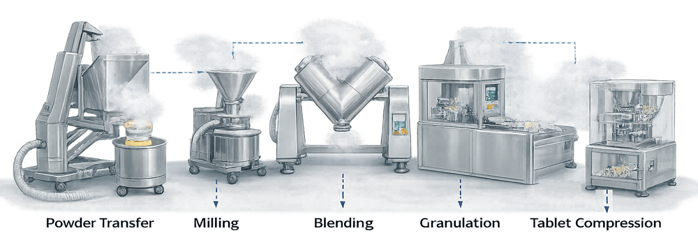
Powder can be released whenever material is opened, poured, transferred, agitated, reduced in size, compressed, discharged, or cleaned. Common generation points include:
- Opening bags, drums, and intermediate bulk containers
- Sampling and dispensing
- Manual charging into equipment
- Vacuum or pneumatic transfer connections
- Milling and screening
- Blender loading and discharge
- Dry-granulation and wet-granulation operations
- Fluid-bed loading, drying, and discharge
- Tablet-press feed frames, die tables, and discharge chutes
- Tablet dedusters
- Capsule-filling dosing and discharge stations
- Coating-solution preparation and tablet handling
- Inspection-machine feed and reject stations
- Filter removal and dust-bin emptying
- Vacuum cleaning and equipment disassembly
The illustration identifies common powder-release points across solid dosage manufacturing.
The amount of airborne dust depends on more than the quantity handled. Particle size, density, moisture, electrostatic behavior, dustiness, transfer height, drop distance, equipment speed, ventilation, and operator technique may all influence dust release.
Related equipment controls are discussed in the articles on dispensing and material handling, pharmaceutical milling, blending equipment, granulation equipment, drying equipment, tablet compression, capsule filling, tablet coating, and solid dosage inspection systems.
Distinct control objectives
Containment-system requirements should begin with a clear statement of the intended control objectives.
| Objective | Primary concern | Examples of evidence |
|---|---|---|
| Product protection | Contamination or cross-contamination of exposed product | Airflow assessment, cleaning controls, material-flow review, environmental controls |
| Operator protection | Inhalation or dermal exposure | Occupational-exposure assessment, personal and area sampling, surrogate testing |
| Room containment | Migration of powder to adjacent spaces | Pressure relationships, smoke studies, surface monitoring, room recovery |
| Source capture | Removal of dust where it is generated | Capture airflow, hood performance, visualization, representative operating tests |
| Environmental protection | Release through exhaust or waste handling | Filtration, discharge monitoring, waste-containment controls |
| Combustible-dust safety | Fire, flash fire, deflagration, or explosion | Material data, hazard analysis, ignition control, explosion protection and isolation |
| GMP equipment control | Reliable and documented operation | DQ, IQ, OQ, equipment-level PQ, calibration, maintenance, change control |
Visible cleanliness is not sufficient evidence of containment. Conversely, an isolated trace of visible powder does not by itself quantify operator exposure. The acceptance method must correspond to the risk being evaluated.
Containment hierarchy
Effective containment normally uses several layers of control.
Closed processing and transfer
The preferred approach is to minimize the opportunity for powder to become airborne. Examples include:
- Closed charging and discharge
- Vacuum transfer
- Sealed intermediate bulk containers
- Split butterfly valves
- Contained docking systems
- Continuous liners
- Enclosed feeders
- Closed sampling arrangements
- Isolators and gloveboxes
Closed equipment can substantially reduce powder release, but its performance depends on connection integrity, gasket condition, operating technique, disconnection controls, cleaning, and waste removal.
Equipment enclosure
An enclosure restricts the movement of released powder and allows extraction air to maintain inward airflow at openings.
Examples include:
- Enclosed tablet presses
- Mill enclosures
- Capsule-filler cabinets
- Gloveboxes
- Restricted-access enclosures
- Contained booths
Access doors, glove ports, transfer openings, cable penetrations, and maintenance panels must be included in the assessment.
Local source capture
Local capture removes dust near the point of release before it can disperse into the room.. Examples include extraction rings, slotted hoods, flanged connections, downdraft work surfaces, and equipment extraction ports.
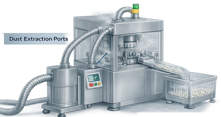
Capture effectiveness depends on:
- Distance between the dust source and capture point
- Hood geometry
- Direction and momentum of the dust cloud
- Operator position
- Obstructions
- Cross-drafts
- Extraction airflow
- Equipment operating state
- Concurrent operation of other branches
Increasing airflow is not always an acceptable correction. Excessive extraction can remove product, disturb weighing, affect equipment operation, increase filter loading, or alter room-pressure relationships.
Room and facility controls
Room-pressure differentials and facility air-handling systems provide an additional control layer. They should not be treated as substitutes for effective source containment.
Negative room pressure may help prevent powder migration to adjacent areas, while positive pressure may be needed for product protection in another application. The selected arrangement must reconcile product, operator, environmental, and facility requirements.
21 CFR 211.46 requires appropriate control of air pressure and dust and requires adequate exhaust or other controls where air contamination occurs during production. It also requires controls over recirculation of production dust when air is returned to production areas.
Personal protective equipment
Respiratory protection and protective clothing may supplement engineering controls. They should not be used to compensate routinely for an inadequately designed containment system.
Selection and use of respiratory protection fall under the site’s occupational-safety and industrial-hygiene programs rather than equipment qualification alone.
Dust-collection system architecture
A dust-collection system commonly includes:
- Dust-generation source
- Equipment enclosure or capture hood
- Extraction connection
- Branch duct
- Balancing or isolation damper
- Main extraction duct
- Pre-separator or cyclone where used
- Filter housing or dust collector
- Filter-cleaning mechanism
- Dust hopper and collection container
- Extraction fan
- Filtered-air exhaust or return
- Monitoring instruments and controls
- Fire and explosion protection where required
A typical system transports dust-laden air from the process source through filtration before the air is exhausted or returned.
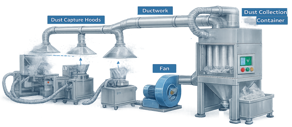
The system boundary should be documented on approved airflow diagrams, duct drawings, equipment layouts, control narratives, and instrument lists.
Interfaces with facility HVAC, process equipment, building-management systems, waste handling, compressed air, electrical power, fire-protection systems, and automation should be identified.
Central and local dust collectors
Central systems
A central collector may serve multiple rooms or pieces of equipment through a common duct network.
Potential advantages include:
- Centralized maintenance
- Reduced equipment within processing rooms
- Shared filtration capacity
- Centralized waste collection
Potential risks include:
- Cross-contamination through common ductwork
- Unbalanced airflow
- Interaction between open and closed branches
- Greater consequence of fan or collector failure
- Powder accumulation in long duct runs
- Complex cleaning and product-change controls
A central extraction network may connect multiple process machines to a shared dust collector.
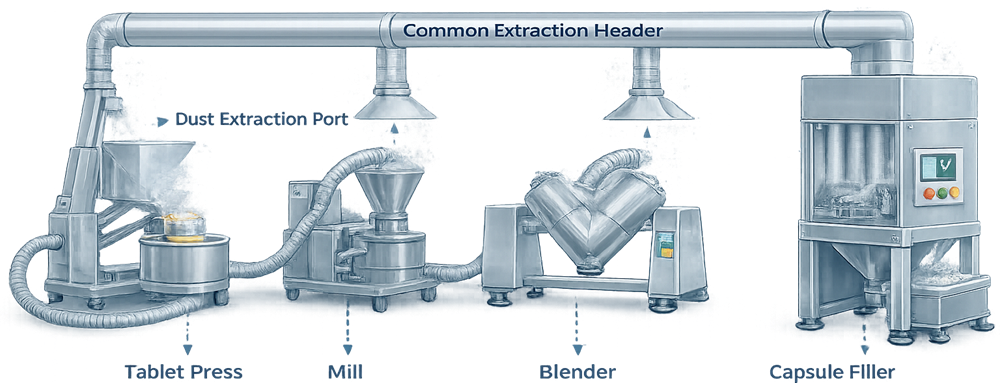
The suitability of a common collector depends on the materials, products, campaign strategy, cleaning approach, duct configuration, filtration, and hazard assessment.
Local systems
A local or dedicated collector serves one machine, room, or process area.
Potential advantages include:
- Shorter duct runs
- Simpler airflow balancing
- Reduced connection between products
- Easier segregation
- More direct association with the process equipment
Potential limitations include:
- Restricted airflow capacity
- More equipment requiring maintenance
- Collector placement within or near the processing area
- More frequent dust-bin handling
- Space and noise constraints
Portable collectors require control of equipment identity, approved location, hose configuration, grounding, filter status, cleaning status, and connection to the correct process.
Capture hoods and extraction connections
Capture devices should be designed around the actual dust-release mechanism. A hood may perform poorly when:
- It is too far from the release point
- Dust travels away from the hood
- An operator stands between the source and hood
- Cross-drafts overcome capture airflow
- The opening is unnecessarily large
- Material or equipment blocks the airflow path
- Flexible hoses collapse or kink
- An access door is left open
- Equipment speed or feed rate exceeds the evaluated condition
A flange or partial enclosure can improve capture without requiring a large increase in airflow. Equipment manufacturers should identify the required extraction conditions at each connection and any operating consequences of excessive or insufficient airflow.
Ductwork and airflow distribution
Ductwork transports contaminated air from the capture point to the collector. Design considerations include:
- Duct diameter and cross-sectional area
- Air velocity
- Pressure loss
- Branch arrangement
- Elbows and transitions
- Flexible-hose length
- Internal surface condition
- Dead legs and low points
- Access for inspection and cleaning
- Grounding and bonding
- Damper location and position control
- Prevention of reverse flow
- Isolation between incompatible materials
- Structural support
- Fire and explosion isolation
Velocity must be sufficient to transport the expected dust without excessive deposition. No universal transport velocity is appropriate for every pharmaceutical powder. The justified range depends on the material, particle properties, duct orientation, system configuration, and hazard assessment.
Airflow should be evaluated under credible combinations of operating branches. A connection that performs adequately when used alone may become ineffective when additional branches are opened.
Fans, dampers, and system balance
The extraction fan must provide the required airflow against the total system resistance.
Fan selection should consider:
- Required flow range
- Static-pressure requirement
- Filter loading
- Maximum and minimum active branches
- Fan speed control
- Motor rating
- Material compatibility
- Noise and vibration
- Cleaning and maintenance
- Safe shutdown
- Hazardous-location requirements where applicable
Variable-frequency drives may maintain a pressure or airflow setpoint as filter resistance changes. The control strategy should define the measured variable, acceptable range, response to sensor failure, upper and lower speed limits, alarm behavior, and safe state.
Balancing dampers should have identified and controlled positions. Undocumented damper adjustment can invalidate the established airflow balance.
Filtration and dust discharge
Dust collectors may use cartridge filters, bag filters, rigid elements, high-efficiency final filters, or combinations of filtration stages. The filtration stage separates captured powder from the extraction air while maintaining the required system airflow.
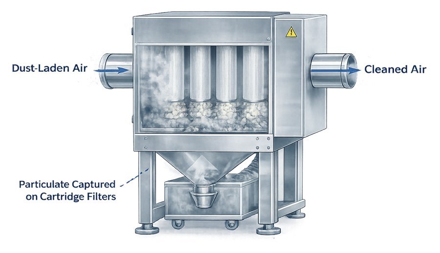
Filter selection should consider:
- Particle-size distribution
- Dust loading
- Required filtration efficiency
- Airflow and pressure loss
- Material compatibility
- Moisture and temperature
- Cleaning method
- Electrostatic properties
- Combustible-dust hazards
- Replacement frequency
- Safe-change requirements
- Disposal method
- Whether filtered air is exhausted or recirculated
HEPA filtration is not automatically required for every dust-collection system. Where it is used, the design should define filter classification, installation, seal arrangement, integrity-test capability, monitoring, replacement, and disposal.
A supplier certificate does not demonstrate that a filter remains correctly installed and undamaged after transportation, installation, operation, or maintenance.
Filter cleaning
Pulse-jet, reverse-air, shaker, or offline cleaning may be used to remove accumulated powder from filter surfaces.
The cleaning arrangement should address:
- Cleaning frequency or trigger
- Compressed-air quality and pressure
- Pulse duration and sequence
- Effect on process-room pressure
- Powder release from the filter
- Hopper discharge
- Failure detection
- Prevention of uncontrolled dust clouds
- Cleaning during production versus offline cleaning
Differential pressure across a filter indicates resistance to airflow. It does not independently prove filtration efficiency or source-capture performance.
Dust collection and removal
Collected powder may discharge into:
- A rigid bin
- A drum
- A flexible bag
- A continuous liner
- A contained transfer vessel
- A wet collection system
Removal of collected dust may be one of the system’s highest-exposure activities. The design should minimize uncontrolled opening, liner detachment, dust re-entrainment, spills, and operator contact.
Collection containers should have defined capacity, status identification, installation verification, fill-level controls where needed, and an approved disposal route.
Return air versus external exhaust
Filtered air may be discharged outside the building or returned to a controlled space.
A recirculation decision should consider:
- Material potency and toxicity
- Sensitization risk
- Cross-contamination potential
- Filter efficiency and integrity
- Failure detection
- Room classification
- Product segregation
- Environmental permits
- Energy use
- Combustible-dust hazards
- Applicable building and fire requirements
Air should not be recirculated solely because a high-efficiency filter is installed. The complete failure scenario, monitoring arrangement, and consequence of filter damage or bypass must be assessed.
Potent compounds and containment-performance testing
Highly potent or sensitizing materials may require isolators, contained transfer devices, safe-change filters, continuous liners, dedicated collectors, or once-through exhaust arrangements.
Occupational exposure limits and occupational exposure bands should be established by qualified toxicology and industrial-hygiene personnel.
Containment-performance studies may use a surrogate powder and representative operations to evaluate airborne release. The protocol should define:
- Surrogate material
- Particle characteristics and dustiness
- Quantity handled
- Equipment configuration
- Operating sequence
- Number and location of samples
- Personal and area sampling
- Sampling duration
- Analytical method
- Background controls
- Recovery and cleaning
- Acceptance criteria
- Statistical treatment
- Deviations and invalid samples
A successful surrogate study supports the evaluated configuration and operating procedure. It should not be generalized automatically to a more potent material, dustier formulation, higher throughput, different operator technique, or modified equipment arrangement.
Combustible-dust hazards
Pharmaceutical powders and excipients may present fire or explosion hazards when sufficiently fine material is dispersed in air and an ignition source is present. OSHA identifies pharmaceuticals among the industries that may handle explosible dusts and recommends assessment of materials, operations, spaces, accumulations, and ignition sources. See the official OSHA combustible-dust overview.
The assessment may require material-specific data such as:
- Explosibility classification
- Maximum explosion pressure
- Dust deflagration index
- Minimum ignition energy
- Minimum explosible concentration
- Minimum ignition temperature
- Limiting oxygen concentration
- Electrical resistivity
- Particle-size distribution
- Moisture content
Published values for a similar material may not represent the actual formulation. Testing should be considered when reliable, representative information is unavailable.
Depending on the hazard analysis, controls may include:
- Grounding and bonding
- Static-dissipative components
- Ignition-source control
- Suitable electrical classification
- Explosion venting
- Explosion suppression
- Flameless venting
- Deflagration isolation
- Spark detection and extinguishment
- Inerting
- Segregated collector location
- Housekeeping and dust-accumulation control
Containment pressure and combustible-dust protection must be coordinated. A rapidly closing isolation device, explosion vent, or suppression system has a different purpose from normal airflow control and requires its own inspection, testing, and maintenance program.
Equipment qualification should verify the installed configuration and specified interfaces. It does not replace the formal combustible-dust hazard analysis or certification required by applicable safety codes.
Instrumentation and control
Typical monitoring points include:
- Airflow at critical extraction connections
- Duct velocity
- Duct static pressure
- Hood or enclosure differential pressure
- Filter differential pressure
- Fan speed
- Fan motor status
- Damper position
- Room differential pressure
- Pulse-cleaning pressure
- Dust-bin level
- Filter or access-door position
- Explosion-protection device status
The control system may provide:
- Start and stop sequencing
- Process-equipment permissives
- Fan-speed control
- Damper control
- Filter-cleaning sequences
- High and low pressure alarms
- Loss-of-airflow alarms
- Bin-full alarms
- Filter-condition alarms
- Safe shutdown
- Event and alarm records
- Trend display
- Maintenance notifications
An extraction permissive may prevent process equipment from operating until acceptable airflow is established. The design should define how the system responds if airflow is subsequently lost.
Alarm limits should be based on the qualified operating range and control objective. A filter differential-pressure alarm should not be described as a direct containment alarm unless a justified relationship has been demonstrated.
Automation used to make GMP decisions should be controlled under the applicable computerized-system and electronic-record requirements. 21 CFR 211.68 addresses controls for automatic, mechanical, and electronic equipment.
Cleaning and cross-contamination control
Containment equipment can prevent powder dispersion during production while still retaining substantial residue internally.
The cleaning boundary may include:
- Equipment enclosures
- Capture hoods
- Extraction ports
- Flexible hoses
- Ductwork
- Dampers
- Collector housings
- Filter supports and seals
- Hoppers
- Dust bins
- Waste connections
- Tools and maintenance parts
Cleaning procedures should define:
- Dry or wet cleaning
- Disassembly requirements
- Vacuum-cleaner configuration
- Prohibited methods such as uncontrolled compressed-air cleaning
- Filter handling
- Waste containment
- Cleaning sequence
- Inspection
- Storage of cleaned parts
- Reassembly
- Cleaning status
- Campaign or product-change requirements
Shared ducts and central collectors require particular attention because they can create connections between products or rooms.
Cleanable design and qualified cleaning functions support contamination control, but they do not replace the evidence required under the site’s cleaning validation approach.
Design qualification
Design qualification should demonstrate that the proposed system satisfies the approved user requirements and risk controls.
The design review should address:
- Intended products and material hazards
- Required control objectives
- Dust-generation sources
- System boundaries
- Capture-device design
- Required airflow at each connection
- Simultaneous-use scenarios
- Duct sizing and pressure-loss calculations
- Filter selection and loading
- Fan capacity
- Exhaust or recirculation strategy
- Dust discharge and waste handling
- Cleaning and maintenance access
- Safe filter replacement
- Instrumentation and alarm strategy
- Process-equipment interlocks
- Facility HVAC interfaces
- Combustible-dust controls
- Automation and data requirements
- Qualification and testing provisions
Supplier calculations and drawings should be reviewed against the actual site configuration rather than accepted as generic evidence.
Supplier testing, FAT, and SAT
Factory acceptance testing may verify:
- Collector construction
- Fan and motor operation
- Control-panel functions
- Alarm logic
- Damper operation
- Filter-cleaning sequence
- Dust-discharge mechanisms
- Documentation
- Software configuration
- Instrument certificates
Site acceptance testing should confirm the system after installation and connection to the actual duct network, utilities, HVAC, and process equipment.
Factory airflow results generally cannot replace site airflow balancing because the final duct lengths, branch arrangements, dampers, filters, room pressures, and connected equipment influence performance.
Installation qualification
Installation qualification should verify:
- Equipment manufacturer, model, and identification
- Collector, fan, motor, and filter installation
- Materials of construction
- Duct routing and branch identification
- Duct size, supports, joints, and access points
- Flexible-hose type and maximum approved configuration
- Damper type, location, identification, and position
- Equipment extraction connections
- Filter type and installation
- Filter seals and retaining arrangements
- Dust-bin and liner interfaces
- Exhaust or return-air destination
- Utilities
- Electrical installation
- Grounding and bonding
- Instrument identification and calibration status
- Control panel and software version
- Alarm and interlock wiring
- Explosion-protection devices and interfaces
- Approved drawings and manuals
- Lubricants and maintenance requirements
- Spare-parts lists
Installation should be compared with approved as-built documentation. Undocumented field changes should be resolved before functional testing.
Operational qualification
Operational qualification demonstrates that the system functions throughout its approved operating range.
Typical OQ tests include:
- Fan start, stop, and direction of rotation
- Fan-speed range
- Damper operation
- Airflow at critical branches
- Duct static pressure
- System balance
- Filter differential-pressure measurement
- Filter-cleaning sequence
- Dust-bin and discharge operation
- Door and access-panel interlocks
- Loss-of-airflow response
- High and low pressure alarms
- Fan or motor failure response
- Instrument-signal failure
- Power interruption and recovery
- Process-equipment permissives
- Local and remote control
- Emergency stop where applicable
- Alarm display, acknowledgment, and recording
- User access and security where applicable
Qualification verifies airflow and pressure at locations that represent source capture, duct transport, and filter condition.
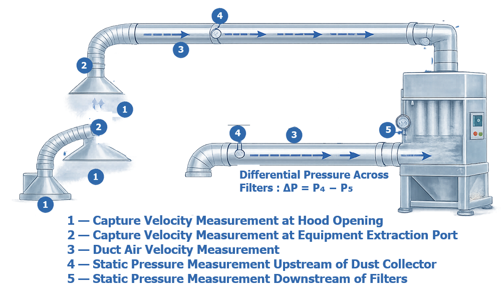
Testing should include credible combinations of active and inactive branches. Where adjustable dampers or fan speeds establish the qualified configuration, their approved settings or control ranges should be documented.
Airflow visualization may demonstrate direction and identify turbulence, leakage, or escape paths. It is qualitative evidence and should not be substituted for quantitative airflow or exposure measurements when those are required.
Equipment-level performance qualification
Equipment-level PQ evaluates the integrated system under representative operating conditions. The study may include:
- Representative equipment and process states
- Minimum and maximum production rates
- Normal charging and discharge
- Opening and closing access points
- Representative operator interventions
- Filter conditions across the approved range
- Worst-case simultaneous branch use
- Dust-bin or liner replacement
- Cleaning and changeover activities
- Smoke or visualization studies
- Surrogate-powder release studies
- Surface or area monitoring where justified
- Recovery after a disturbance
Acceptance criteria should correspond to the claimed function.
Examples include:
- Required airflow maintained at each critical connection
- Inward airflow maintained at defined openings
- No unacceptable escape during representative operations
- Alarms and interlocks respond before loss of control
- Filter differential pressure remains within the qualified range
- Powder is transferred to the collection container without uncontrolled release
- The system returns to its controlled state after normal interventions
Equipment-level PQ does not by itself validate the complete manufacturing process or demonstrate compliance with occupational-exposure limits. Product-specific process validation and industrial-hygiene studies remain separate activities.
Qualification versus other verification activities
| Activity | What it demonstrates | What it does not automatically demonstrate |
|---|---|---|
| Equipment qualification | Correct installation and reliable operation within approved ranges | Product-specific process performance |
| Airflow balancing | Required distribution through the duct network | Acceptable personal exposure |
| Smoke visualization | Airflow direction and visible escape paths | Quantitative containment |
| Filter integrity testing | Installed filter and seal integrity under the test conditions | Capture at the process source |
| Surrogate containment testing | Release performance for the evaluated task and configuration | Performance for every product and operating condition |
| Industrial-hygiene monitoring | Worker exposure under sampled conditions | GMP cleaning effectiveness |
| Cleaning validation | Residue control for the approved cleaning process | Combustible-dust safety |
| Dust hazard analysis | Fire and explosion hazards and required safeguards | GMP qualification of all operating functions |
| Process validation | Reproducible manufacturing-process performance | Condition of every dust-control component |
Common failure modes and controls
| Failure mode | Possible consequence | Typical control |
|---|---|---|
| Blocked or heavily loaded filter | Reduced airflow and source capture | Differential-pressure monitoring, airflow alarm, maintenance |
| Damaged filter or seal | Particulate release or bypass | Installation inspection, integrity testing where required |
| Incorrect damper position | Branch imbalance | Identified settings, position indication, restricted adjustment |
| Flexible hose collapse or disconnection | Loss of extraction | Approved hose, inspection, connection verification |
| Duct leakage | Powder release or loss of airflow | Installation inspection, pressure or leakage testing |
| Dust accumulation in ductwork | Contamination or fire hazard | Transport design, access, inspection, cleaning |
| Fan failure or incorrect rotation | Loss of system airflow | Rotation check, status feedback, interlock |
| Open access door | Loss of enclosure containment | Door alarm or interlock, operating procedure |
| Full dust bin | Blockage or uncontrolled discharge | Level indication, inspection, replacement frequency |
| Failed pulse-cleaning system | Increasing filter resistance | Pressure monitoring, sequence alarm, maintenance |
| Incorrect replacement filter | Inadequate performance or incompatibility | Approved parts, identity verification, change control |
| Alarm bypass or disabled interlock | Operation without containment | Access control, bypass management, alarm review |
| Uncontrolled branch addition | Loss of airflow to existing users | Engineering assessment, rebalance, requalification |
| Failed explosion-isolation device | Hazard propagation | Inspection, testing, certified maintenance |
| Loss of grounding | Static ignition risk | Continuity checks, inspection, maintenance |
Calibration and preventive maintenance
Instruments used to establish airflow, pressure, alarm status, or acceptance decisions should be managed under the applicable calibration program and metrology control.
The maintenance program may include:
- Fan and motor inspection
- Bearing and vibration checks
- Belt or coupling inspection
- Filter inspection and replacement
- Seal and gasket replacement
- Pulse-cleaning system inspection
- Compressed-air checks
- Damper and actuator inspection
- Duct inspection
- Flexible-hose replacement
- Grounding-continuity checks
- Dust-bin and liner-interface inspection
- Alarm and interlock testing
- Explosion-protection device inspection
- Instrument calibration
- Software backup and configuration control
Maintenance frequency should reflect equipment criticality, supplier recommendations, operating hours, dust loading, monitoring trends, failure history, and material hazards. Broader lifecycle controls are discussed in preventive maintenance and equipment reliability.
Continued verification and trending
Useful lifecycle indicators include:
- Filter differential-pressure trend
- Fan speed required to maintain airflow
- Branch airflow or pressure
- Frequency of high or low airflow alarms
- Filter replacement frequency
- Dust-bin filling rate
- Pulse-cleaning frequency
- Airflow-balance deviations
- Visible dust observations
- Surface-monitoring results
- Containment-study results
- Duct-cleaning findings
- Maintenance and repair history
- Repeated hose, seal, or damper failures
- Operator-exposure monitoring results where applicable
A rising fan-speed requirement or increasing filter differential pressure may indicate progressive loading. A decreasing pressure drop may indicate filter damage, seal failure, bypass, or a change in system resistance. Trends should be interpreted together rather than as isolated values.
Change control and requalification
Changes should be assessed before implementation.
Examples include:
- Introduction of a more potent or dustier material
- Change in particle-size distribution
- Increased batch size or throughput
- New dust-generation source
- New or relocated equipment connection
- Modified hood or enclosure
- Duct extension or rerouting
- New branch or damper
- Flexible-hose change
- Fan or motor replacement
- Filter-media or filter-grade change
- Collector relocation
- Change from external exhaust to recirculation
- HVAC or room-pressure modification
- Revised alarm or interlock
- Control-software change
- Modified dust-discharge arrangement
- Change to explosion protection
- New cleaning method
- Repeated airflow, filter, or containment failures
The impact assessment should determine whether document revision, calibration, airflow balancing, functional testing, containment testing, industrial-hygiene assessment, cleaning studies, or partial or full requalification is required.
Requalification should be based on the affected functions and risks rather than performed automatically as a complete repetition of the original qualification.
Periodic review
Periodic review should confirm that:
- The intended use remains current
- Products and material hazards remain within the assessed range
- As-built drawings match the installed system
- Approved damper and fan settings remain controlled
- Instruments remain calibrated
- Preventive maintenance is current
- Filter changes are documented
- Alarms and deviations have been evaluated
- Duct and collector inspections are satisfactory
- Containment or exposure studies remain applicable
- Combustible-dust safeguards remain inspected and maintained
- Changes have received appropriate qualification
- Recurring failures have been addressed
- Procedures and training remain current
Periodic review should use operating and maintenance data to determine whether performance is stable or whether additional investigation, testing, or requalification is needed.
Documentation and traceability
The lifecycle record should include, as applicable:
- User requirements specification
- Risk assessments
- Containment strategy
- Occupational-hazard assessment
- Combustible-dust hazard analysis
- Design qualification
- Supplier drawings and calculations
- Airflow and duct diagrams
- Instrument and alarm lists
- Control narrative
- Filter specifications
- Material certificates
- FAT and SAT records
- IQ, OQ, and PQ protocols and reports
- Airflow-balancing reports
- Filter-integrity records
- Containment-study reports
- Calibration records
- Cleaning procedures
- Maintenance procedures
- Dust-disposal procedures
- Deviations and investigations
- Change controls
- Requalification records
- Periodic reviews
- Training records
- Current as-built drawings
Traceability should connect each critical user requirement and identified risk to its design control, verification activity, acceptance result, and lifecycle control.
Regulatory context
The following requirements are particularly relevant:
- 21 CFR 211.42 addresses building design and operations intended to prevent contamination and mix-ups.
- 21 CFR 211.46 addresses ventilation, air pressure, dust control, filtration, exhaust, and recirculation.
- 21 CFR 211.63 requires equipment to be of appropriate design and adequate size and to be suitably located.
- 21 CFR 211.67 addresses equipment cleaning and maintenance.
- 21 CFR 211.68 addresses automatic, mechanical, and electronic equipment.
- The OSHA combustible-dust resource describes fire and explosion hazards associated with finely divided combustible materials, including pharmaceutical powders.
Applicable occupational-safety, environmental, fire, building, electrical, and insurance requirements should also be identified for the specific installation.
Conclusion
Pharmaceutical powder containment and dust collection require coordinated control of the powder source, enclosure, capture device, duct network, filtration, fan, waste discharge, room interfaces, monitoring, and operator activities.
Effective source capture does not by itself prove acceptable occupational exposure, cleaning effectiveness, product protection, or combustible-dust safety. Each objective requires suitable risk assessment and evidence.
Lifecycle qualification should demonstrate that the system is correctly designed, installed, operated, monitored, maintained, and changed within approved limits. Continued verification, preventive maintenance, filter management, containment studies, and risk-based requalification help ensure that performance remains reliable throughout the equipment lifecycle.